This thread has been locked.

If you have a related question, please click the "Ask a related question" button in the top right corner. The newly created question will be automatically linked to this question.

How to enable Power Save mode for CC2650STK when device is idle ?

Other Parts Discussed in Thread: CC2650STK, SYSBIOS

Hi, I have pasted code below which I am using for duty  cycle of 10 seconds. My questions are as following.

1) I have inserted Power_enablePolicy() function at the start of main code. Is this correct way of implementing Power saving mode for CC2650STK or is there other way to implement way for this policy.

2) The following structure has to be called explicitly in main function OR once we call  Power_enablePolicy() the structure gets initialized automatically ? If I  add this structure in main() function, it gives errors.

const PowerCC26XX_Config PowerCC26XX_config = {
		.policyInitFxn = NULL,
		.policyFxn = &PowerCC26XX_standbyPolicy,
		.calibrateFxn = &PowerCC26XX_noCalibrate,         // default is &PowerCC26XX_calibrate
		.enablePolicy = TRUE, .calibrateRCOSC_LF = FALSE, // default is TRUE
		.calibrateRCOSC_HF = FALSE,                       // default is TRUE
}

3) In code heartBeatFxn() which runs forever, I have implemented Task_sleep with duty cycle 10 seconds. So led turns on and off turn by turn after every 10 seconds. So, my purpose is to execute Power save mode when Task_sleep is in execution.

4)Do we have to make any changes in empty_min.cfg for implementing power policy?

5) I just want to be sure that Policy for power save gets executed in this sleep condition. Please provide explained answers as there is nothing given how to apply this policy in pdf of power-management.pdf neither do TI has any blog how to implement it.


/*
 *  ======== empty_min.c ========
 */
/* XDCtools Header files */
#include <xdc/std.h>
#include <xdc/runtime/System.h>

/* BIOS Header files */
#include <ti/sysbios/BIOS.h>
#include <ti/sysbios/knl/Task.h>

/* TI-RTOS Header files */
// #include <ti/drivers/I2C.h>
#include <ti/drivers/PIN.h>
// #include <ti/drivers/SPI.h>
// #include <ti/drivers/UART.h>
// #include <ti/drivers/Watchdog.h>

/* Board Header files */
#include "Board.h"

/* Power Management Header Files */
#include <ti/drivers/Power.h>
#include <ti/drivers/power/PowerCC26XX.h>

#define TASKSTACKSIZE   512

Task_Struct task0Struct;
Char task0Stack[TASKSTACKSIZE];

/* Pin driver handle */
static PIN_Handle ledPinHandle;
static PIN_State ledPinState;

/*
 * Application LED pin configuration table:
 *   - All LEDs board LEDs are off.
 */
PIN_Config ledPinTable[] = {
    Board_LED0 | PIN_GPIO_OUTPUT_EN | PIN_GPIO_LOW | PIN_PUSHPULL | PIN_DRVSTR_MAX,
    Board_LED1 | PIN_GPIO_OUTPUT_EN | PIN_GPIO_LOW | PIN_PUSHPULL | PIN_DRVSTR_MAX,
    PIN_TERMINATE
};

/*
 *  ======== heartBeatFxn ========
 *  Toggle the Board_LED0. The Task_sleep is determined by arg0 which
 *  is configured for the heartBeat Task instance.
 */
Void heartBeatFxn(UArg arg0, UArg arg1)
{
    while (1) {
        Task_sleep((UInt)arg0); // Want sensortag to be in deep sleep mode
        PIN_setOutputValue(ledPinHandle, Board_LED0,
                           !PIN_getOutputValue(Board_LED0));
    }
}

/*
 *  ======== main ========
 */
int main(void)
{
	//Enable Power Policy
	Power_enablePolicy();

    Task_Params taskParams;

    /* Call board init functions */
    Board_initGeneral();
    // Board_initI2C();
    // Board_initSPI();
    // Board_initUART();
    // Board_initWatchdog();

    /* Construct heartBeat Task  thread */
    Task_Params_init(&taskParams);
    taskParams.arg0 = 10000;
    taskParams.stackSize = TASKSTACKSIZE;
    taskParams.stack = &task0Stack;
    Task_construct(&task0Struct, (Task_FuncPtr)heartBeatFxn, &taskParams, NULL);

    /* Open LED pins */
    ledPinHandle = PIN_open(&ledPinState, ledPinTable);
    if(!ledPinHandle) {
        System_abort("Error initializing board LED pins\n");
    }else{
    	System_printf("Initialized board LED Pins\n");
    }

    PIN_setOutputValue(ledPinHandle, Board_LED1, 1);

    /* Start BIOS */
    BIOS_start();

    return (0);
}

  • In BLE examples, you only need to define POWER_SAVING in compile option and it would do power management for you.

  • I have defined POWER_SAVING as an predefined symbol in advanced options of ARM compiler to make power policy on. is this correct way to make power policy enable ?

    After making this We tested above code to make current consumption measurements. We found following results. I have attached screenshot for power consumption below. My measurements are -->> it is consuming 8 mA current when LED is in OFF state an 11 mA when LED is in ON state.

    So, my question is why there is very high current consumption when LED is in OFF state (8mA). It should be very low like in the range of micro-Amps is we are applying power policy. I think we are unable to implement power policy properly.

    Please let me know elaboreate solution if I am making any mistakes.

    Screenshot:-

  • Jayesh Sarode said:
    I have defined POWER_SAVING as an predefined symbol in advanced options of ARM compiler to make power policy on. is this correct way to make power policy enable ?

    That only works for the BLE example code, which is set up for reduced power consumption when POWER_SAVING is defined. The empty-min project template your code is based on doesn't do that.

    Unfortunately TI don't provide a version of empty_min with proper low-power setup. You either have to modify empty_min to cut power consumption, or try to understand the complicated BLE sample and strip out the parts you don't need. If you want to take the first option, then this post might be useful: http://forum.43oh.com/topic/8864-cc2650-sensortag-low-power-checklist/

  • In that link provided I can not go to the screenshot 1. I have attached my system screenshot.

  • Is your example based on any TI BLE Stack example? As Jayesh replied, POWER_SAVING only works for TI BLE example. If your application is not implemented based on BLE example, it won't work.
  • Jayesh Sarode said:

    In that link provided I can not go to the screenshot 1. I have attached my system screenshot.

    Ah, yes, the pictures only show up when logged in to a 43oh forum account.

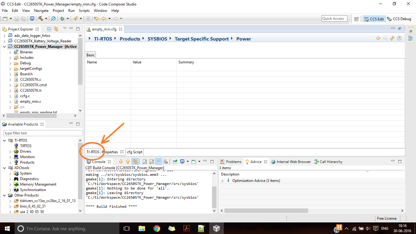
    If you click on the TI-RTOS tab (just above the console view in your screenshot) you should get a page with a checkbox "Invoke Power Policy function when all threads are blocked". Uncheck that, and go to the BIOS Overview page (TI-RTOS > Products > SYSBIOS > BIOS - System Overview) and click on the "Idle" box in the threads area. That should take you to the page where you can set up the custom idle task.

    With that set up as described in the 43oh thread you'll be able to put a breakpoint in the idle task and easily see whether it's being run as expected.

  • Hi Robert,

    I really did not understand your reply. I tried to find out that checkbox option for "Invoke Power Policy function when all threads are blocked".
    But could not find it neither I understood your comment :- Ah, yes, the pictures only show up when logged in to a 43oh forum account.

    Can you please elaborate your reply so that I will be able to find out that checkbox?
  • Jayesh Sarode said:

    [...] neither I understood your comment :- Ah, yes, the pictures only show up when logged in to a 43oh forum account.

    The post I linked to on 43oh.com has pictures embedded, but you can only see them if you're a member of that forum. Non-members only get to see the text without any pictures.

    Can you post another screenshot showing what happens if you click on the TI-RTOS tab marked on the image below:

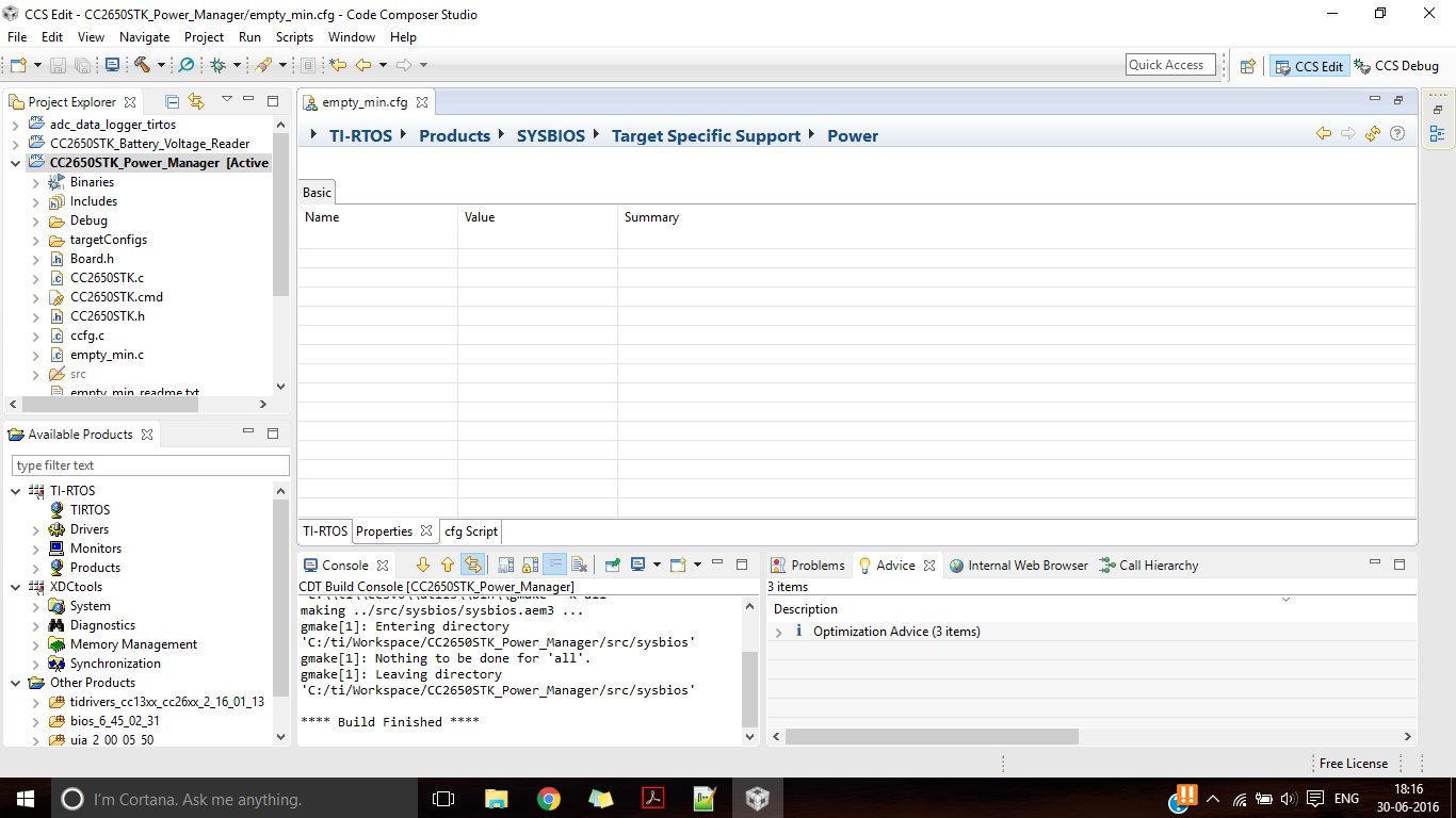
  • If I click on TI-RTOS tab, it takes me to the homepage. I did not understand what is 43oh.com and how it is associated with CCS.

    Screenshot attached:- 

  • Jayesh,

    43oh.com is a community where technical discussions/forums about various TI parts are held. It was started by MSP430 enthusiasts, hence the name.

    In any case, if your ultimate goal is to implement a BLE solution, I recommend starting from a sample application in our SDK such as simple BLE peripheral. As Robert and YiKai have pointed out, all BLE sample apps have power management enabled/set up out of the box.

    Attached is a sample *.cfg file that the BLE SDK uses. This is what Robert is guiding you to modify:

    cc2640.cfg

  • Hi Sean,

    I want very simple toggling led example with duty cycle 10 seconds with power management enabled.

    i.e  whenever led is in off state, current consumption should be least. Currently we are getting 8mA consumption when led is in off state which is not at all acceptable

    I tried to modify sensortag_cc2650stk_app by modifying its main.c as follows. It works when powered with usb with debugger devpack on it. But whenever I remove debugger devpack and power CC2650STK, I can not see the functioning of the code.

    Please help me out on this as I am trying this very easy example from past week neither there is complete help from your side.

    Code is attached as below:-

    /*
     * Copyright (c) 2015-2016, Texas Instruments Incorporated
     * All rights reserved.
     *
     * Redistribution and use in source and binary forms, with or without
     * modification, are permitted provided that the following conditions
     * are met:
     *
     * *  Redistributions of source code must retain the above copyright
     *    notice, this list of conditions and the following disclaimer.
     *
     * *  Redistributions in binary form must reproduce the above copyright
     *    notice, this list of conditions and the following disclaimer in the
     *    documentation and/or other materials provided with the distribution.
     *
     * *  Neither the name of Texas Instruments Incorporated nor the names of
     *    its contributors may be used to endorse or promote products derived
     *    from this software without specific prior written permission.
     *
     * THIS SOFTWARE IS PROVIDED BY THE COPYRIGHT HOLDERS AND CONTRIBUTORS "AS IS"
     * AND ANY EXPRESS OR IMPLIED WARRANTIES, INCLUDING, BUT NOT LIMITED TO,
     * THE IMPLIED WARRANTIES OF MERCHANTABILITY AND FITNESS FOR A PARTICULAR
     * PURPOSE ARE DISCLAIMED. IN NO EVENT SHALL THE COPYRIGHT OWNER OR
     * CONTRIBUTORS BE LIABLE FOR ANY DIRECT, INDIRECT, INCIDENTAL, SPECIAL,
     * EXEMPLARY, OR CONSEQUENTIAL DAMAGES (INCLUDING, BUT NOT LIMITED TO,
     * PROCUREMENT OF SUBSTITUTE GOODS OR SERVICES; LOSS OF USE, DATA, OR PROFITS;
     * OR BUSINESS INTERRUPTION) HOWEVER CAUSED AND ON ANY THEORY OF LIABILITY,
     * WHETHER IN CONTRACT, STRICT LIABILITY, OR TORT (INCLUDING NEGLIGENCE OR
     * OTHERWISE) ARISING IN ANY WAY OUT OF THE USE OF THIS SOFTWARE,
     * EVEN IF ADVISED OF THE POSSIBILITY OF SUCH DAMAGE.
     */
    
    /*
     *  ======== empty_min.c ========
     */
    /* XDCtools Header files */
    #include <xdc/std.h>
    #include <xdc/runtime/System.h>
    
    /* BIOS Header files */
    #include <ti/sysbios/BIOS.h>
    #include <ti/sysbios/knl/Task.h>
    
    /* TI-RTOS Header files */
    // #include <ti/drivers/I2C.h>
    #include <ti/drivers/PIN.h>
    // #include <ti/drivers/SPI.h>
    // #include <ti/drivers/UART.h>
    // #include <ti/drivers/Watchdog.h>
    
    /* Board Header files */
    #include "Board.h"
    
    /* Power Management Header Files */
    #include <ti/drivers/Power.h>
    #include <ti/drivers/power/PowerCC26XX.h>
    //#include <ti/sysbios/family/arm/cc26xx/Power.h>
    
    #define TASKSTACKSIZE   512
    
    Task_Struct task0Struct;
    Char task0Stack[TASKSTACKSIZE];
    
    /* Pin driver handle */
    static PIN_Handle ledPinHandle;
    static PIN_State ledPinState;
    
    /*
     * Application LED pin configuration table:
     *   - All LEDs board LEDs are off.
     */
    PIN_Config ledPinTable[] = {
    	Board_LED0 | PIN_GPIO_OUTPUT_EN | PIN_GPIO_LOW | PIN_PUSHPULL | PIN_DRVSTR_MAX,
    	Board_LED1 | PIN_GPIO_OUTPUT_EN | PIN_GPIO_LOW | PIN_PUSHPULL | PIN_DRVSTR_MAX,
    	PIN_TERMINATE
    };
    
    /*
     *  ======== heartBeatFxn ========
     *  Toggle the Board_LED0. The Task_sleep is determined by arg0 which
     *  is configured for the heartBeat Task instance.
     */
    Void heartBeatFxn(UArg arg0, UArg arg1) {
    	while (1) {
    		Task_sleep((UInt) arg0); // Want sensortag to be in deep sleep mode
    		PIN_setOutputValue(ledPinHandle, Board_LED0, !PIN_getOutputValue(Board_LED0));
    	}
    }
    
    /*
    void idleFxn()
    {
        Power_standbyPolicy(); // Breakpoint this line to check that the policy is getting called on idle
    }
    */
    
    /*
     *  ======== main ========
     */
    int main(void) {
    
    	Task_Params taskParams;
    
    	/* Call board init functions */
    	Board_initGeneral();
    
    	// Board_initI2C();
    	// Board_initSPI();
    	// Board_initUART();
    	// Board_initWatchdog();
    
    	/* Construct heartBeat Task  thread */
    	Task_Params_init(&taskParams);
    	taskParams.arg0 = 10000;
    	taskParams.stackSize = TASKSTACKSIZE;
    	taskParams.stack = &task0Stack;
    	Task_construct(&task0Struct, (Task_FuncPtr) heartBeatFxn, &taskParams, NULL);
    
    	/* Open LED pins */
    	ledPinHandle = PIN_open(&ledPinState, ledPinTable);
    	if (!ledPinHandle) {
    		System_abort("Error initializing board LED pins\n");
    	} else {
    		System_printf("Initialized board LED Pins\n");
    	}
    
    	PIN_setOutputValue(ledPinHandle, Board_LED1, 0);
    
    
    	/* Start BIOS */
    	BIOS_start();
    
    	return (0);
    }
    

  • Jayesh,

    I understand your intended use case. Did you look at the cfg file I sent you? You need to enable to power policy/idle function in the RTOS.
  • Hi,

    I have added and modified the .cfg file and code to implement power policy for the toggling led example. I can see that idle loop gets executed which is proof that power policy is implemented. But, still when LED is in off state current consumption is 3.5 to 4 mA. It should be in proximity to 0.1 to 0.3 mA. We really want to reduce this consumption else there is no use of policy as even without power policy implementation, the readings are same.

    Let me know whether I am making any mistakes in implementing it. My updated code for .cfg file and main code have been attached

    Main code:-

    /*
     *  ======== empty_min.c ========
     */
    /* XDCtools Header files */
    #include <xdc/std.h>
    #include <xdc/runtime/System.h>
    
    /* BIOS Header files */
    #include <ti/sysbios/BIOS.h>
    #include <ti/sysbios/knl/Task.h>
    
    /* TI-RTOS Header files */
    // #include <ti/drivers/I2C.h>
    #include <ti/drivers/PIN.h>
    // #include <ti/drivers/SPI.h>
    // #include <ti/drivers/UART.h>
    // #include <ti/drivers/Watchdog.h>
    
    /* Board Header files */
    #include "Board.h"
    
    /* Power Management Header Files */
    #include <ti/drivers/Power.h>
    #include <ti/drivers/power/PowerCC26XX.h>
    //#include <ti/sysbios/family/arm/cc26xx/Power.h>
    
    #define TASKSTACKSIZE   512
    
    Task_Struct task0Struct;
    Char task0Stack[TASKSTACKSIZE];
    
    /* Pin driver handle */
    static PIN_Handle ledPinHandle;
    static PIN_State ledPinState;
    
    /*
     * Application LED pin configuration table:
     *   - All LEDs board LEDs are off.
     */
    PIN_Config ledPinTable[] = {
        Board_LED0 | PIN_GPIO_OUTPUT_EN | PIN_GPIO_LOW | PIN_PUSHPULL | PIN_DRVSTR_MAX,
        Board_LED1 | PIN_GPIO_OUTPUT_EN | PIN_GPIO_LOW | PIN_PUSHPULL | PIN_DRVSTR_MAX,
        PIN_TERMINATE
    };
    
    void myIdleFunc(){
    	System_printf("Idle loop running\n");
    	PowerCC26XX_standbyPolicy();
    }
    
    /*
     *  ======== heartBeatFxn ========
     *  Toggle the Board_LED0. The Task_sleep is determined by arg0 which
     *  is configured for the heartBeat Task instance.
     */
    Void heartBeatFxn(UArg arg0, UArg arg1)
    {
        while (1) {
            Task_sleep((UInt)arg0); // Want sensortag to be in deep sleep mode
            PIN_setOutputValue(ledPinHandle, Board_LED0,
                               !PIN_getOutputValue(Board_LED0));
        }
    }
    
    /*
     *  ======== main ========
     */
    int main(void)
    {
    	Power_enablePolicy();
    
        Task_Params taskParams;
    
        /* Call board init functions */
        Board_initGeneral();
        // Board_initI2C();
        // Board_initSPI();
        // Board_initUART();
        // Board_initWatchdog();
    
        /* Construct heartBeat Task  thread */
        Task_Params_init(&taskParams);
        taskParams.arg0 = 10000;
        taskParams.stackSize = TASKSTACKSIZE;
        taskParams.stack = &task0Stack;
        Task_construct(&task0Struct, (Task_FuncPtr)heartBeatFxn, &taskParams, NULL);
    
        /* Open LED pins */
        ledPinHandle = PIN_open(&ledPinState, ledPinTable);
        if(!ledPinHandle) {
            System_abort("Error initializing board LED pins\n");
        }else{
            System_printf("Initialized board LED Pins\n");
        }
    
        /* Start BIOS */
        BIOS_start();
    
        return (0);
    }
    

    .cfg file has been attached as it is quite big.empty_min.cfg

  • Hi,

    It doesn't look like you are calling Power_init(). Can you try that.

    Another thing is that there are other sensors and hardware on the sensortag that consume power when not placed in a low power state.
    For reference, can you manually put the device into standby (using the power API) and measure your current. This will give you a good baseline to compare your measurements to.
  • Hi ,
    i wanted to know if the Power_saving predefined symbols can be used in the spp_ble code as my code works fine when the power_saving is not enabled but stops to work if it is enabled,i wanted to figure out what the problem was
  • Hello,

    The issues you are seeing seem like they may be un-related to Jayesh's. Can you create a new thread? In any case, I believe that POWER_SAVING requires extra handshaking lines (MRDY, SRDY) with SPP over BLE, thus you will need to connect these lines to make things work.