This thread has been locked.

If you have a related question, please click the "Ask a related question" button in the top right corner. The newly created question will be automatically linked to this question.

TIDA-00374 board does send any BLE packets

Other Parts Discussed in Thread: TIDA-00374, CC2650STK

I have a TIDA-00374 board. It is not sending any ADV_NONCONN_IND packets. 

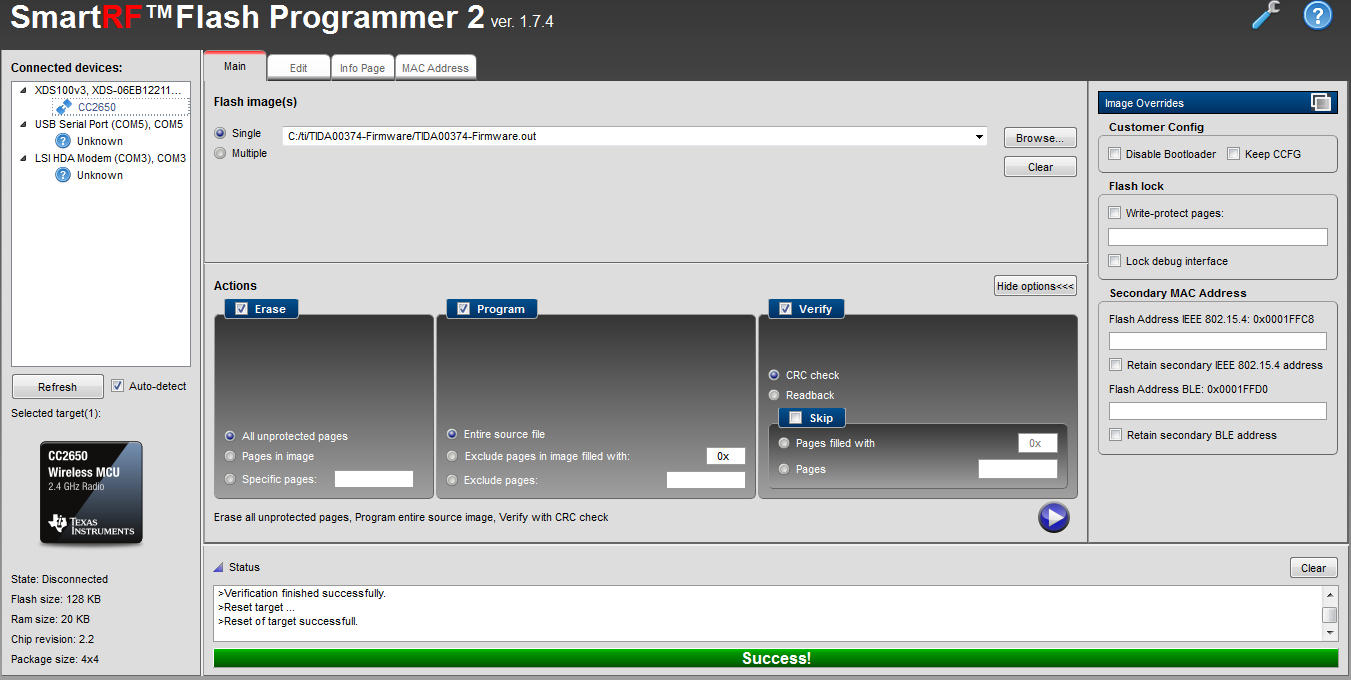
I downloaded Flash Programmer 2 so that I could reimage the target with TIDA00374-Firmware.out.  I downloaded TIDA00374-Firmware.out from 

http://www.ti.com/tool/TIDA-00374

but when I try to image it - it gives error message on Flash Programmer 2 - 

>Initiate access to target: COM5.
>No response from device. Device may not be in bootloader mode. Reset device and try again.
If problem persists, check connection and baud rate.
>Connecting over serial bootloader failed: No response from device. Device may not be in bootloader mode. Reset device and try again.
If problem persists, check connection and baud rate.
>Failed to create device object.

The sensor TIDA-00374 used to work till yesterday. Yesterday I wanted to single step through the code using debugger from CCS. Once I tried to load the debugger - TIDA-00374 device has stopped sending any  ADV_NONCONN_IND packets.

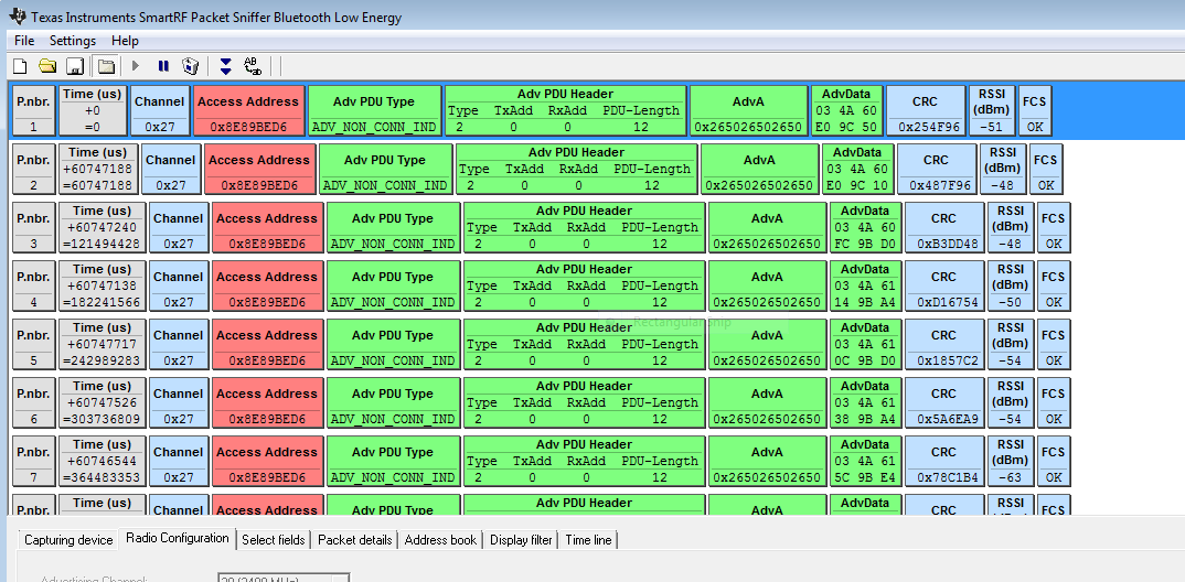
Before I was able to capture the ADV_NONCONN_IND packets from the TIDA-00374 using SmartRF packet sniffer.

Please let me know how I can recover the  TIDA-00374 device.

Much Thanks


  • If you use Flash Programmer 2, does it recognize your TIDA-00374?
  •  YK - This is what my Flash Programmer window looks like. The CPU points to 2650 which is the CPU for TIDA-00374.

    It says successful now but the TIDA-00374 is still not sending out any BLE packets. 

  • Had you ever downloaded TIDA00374-Firmware.out to your board and see it worked?
  • TIDA-00374 used to work before. I wanted to single step through the code using CCS. After that it has stopped working.

    So I tried downloading the TIDA00374-Firmware.out from TI website. After downloading this to the target board, as I have shown above - it still doesn't work.

    Thanks.

  • That's strange. Try to do a mass erase to your TIDA00374 design and download FW to test again.
  • Is the "mass erase" option - the following on the Smart RF Flash Programmer

    Erase section -

    Pages in image

    This is the only option I see that is close to "mass erase". If that's the case - I did that and the TIDA-00374 still doesn't send out any BLE packets.

    Thanks

  • YK - Let me know your thoughts on the information, I have provided above.

    Thanks

  • Tony,

    Assuming the firmware has been flashed, can you confirm what are you jumper settings?  For correct operation, the JTAG must be disconnected, J1 shorted with jumper and coin cell battery installed, and J2 open.  If any of the jumpers are set incorrectly or JTAG is still connected, you will not see the advertisement packet.

    If you want to single step the code using CCS, you'll need to connect JTAG and short J2.  Just remember to remove JTAG and J2 after debugging or loading the code. 

    --Christina

  • Christina - Attached is the picture of the current TIDA-00374 board. With this I'm unable to get any packets on the TI BLuetooth capture device. 

    I connected another BLE device from Motorola and I'm getting BLE ADV_NONCONN_IND packets so I know that the capture device is working.

    Let me know if my jumper settings are incorrect.

    Thanks

  • TIDA-00374 is a reference design so I don't have the HW to help checking your issue. If you are studying BLE function, I would suggest you to use CC2650STK,
  • Tony,

    You have the jumpers set incorrectly.  In the picture, you have J2 shorted and J1 open.  You want the opposite: J2 open and J1 shorted.

    When J1 is shorted, it connects the coin cell battery to the rest of the board.  Since it is open, the device does not have any power. 

    --Christina

  • Christina - Here is the picture of what you suggested. It still doesn't send out any BLE packets. 

    Thanks for all your help.

  • Tony,

    Your jumpers look right.

    Couple more things to check:
    - I am assuming you are using the latest TIDA-00374 firmware. Can you confirm that the BLE sniffer is set to channel 39? The original firmware shipped with TIDA-00374 used channel 37. In the updated firmware, it has been changed to channel 39.
    - To verify that the board is working, can you probe the I2C SCL or SDA signals? You should see I2C pins toggling every minute.

    --Christina
  • Christina - My channel was set to 37 for sniffer. Based on your recommendation I have set it to channel 39.  Here is what I'm seeing on Channel 39. Is this what the sensor is supposed to send. If that's correct, could you please help me interpret the AdvData and also where in source code  these values are being filled into.

    Much thanks for all your help.

  • Tony,

    You are seeing the TIDA-00374 packets correctly.

    The packet is 6 bytes is shown in the AdvData field.

    • Board ID (2 bytes): Value "374" in hex
    • Raw HDC Temperature (2 bytes)
    • Raw HDC Humidity (2 bytes)

    The packet is filled using the "packet" array in main.c. Below is the code snippet from main.c.

    packet[0] = 03;
    packet[1] = 74;
    packet[2] = HDC_data[0];
    packet[3] = HDC_data[1];
    packet[4] = HDC_data[2];
    packet[5] = HDC_data[3];

    --Christina

  • Christina - Thanks for your help. To calculate the absolute value of temperature and humidity - Should we use the information from this link

    www.ti.com/.../hdc1010.pdf

    I'm attaching a snippet from the above pdf. The temperature and humidity values in the register are 14 bits but the values that you are transporting is only 8 bits.

    Are the remaining 6 bits unused.

    Also if we want to debug the software - should we change the jumper settings to be J2 shorted and J1 open. Let us know.

    Much thanks for all your help.

  • Yes, the snippet is correct. You'll perform those calculated on the raw data sent by the BLE advertisement packet.

    As mentioned in the above post, the packet sends the following:
    - Board ID (2 bytes): Value "374" in hex
    - Raw HDC Temperature (2 bytes)
    - Raw HDC Humidity (2 bytes)

    That means it sends 2 bytes or 16 bits for temperature/humidity. No data is lost. The byte order is MSB followed by LSB.

    When debugging, that is correct. You want to shunt J2. For more information, see Section 5.2 in the TIDA-00374 design guide.
  • Christina - My bad. That's correct regarding register information.

    Sincere thanks for all your help.

  • Christina - I'm trying to increase the frequency at which the BLE packets are being sent. I want to send one BLE packet that contains temperature and humidity settings every second.

    In main.c, I can see PACKET_INTERVAL being defined as 

    #define PACKET_INTERVAL 4000000*0.01f

    What is the resolution of this value.

    Also I looked at definition of this RF_getCurrentTime - but not sure how the value of current time is calculated. Could you point to Register spec that explains this.

    Please let us know how we could send one BLE packet every second.

    Much thanks and Happy New Year.

    uint32_t RF_getCurrentTime(void)
    {
    if (bRadioActive)
    {
    return HWREG(RFC_RAT_BASE+RFC_RAT_O_RATCNT);
    }
    else
    {
    uint64_t nRtc;
    nRtc = AONRTCCurrent64BitValueGet();
    // Conservatively assume that we are just about to increment the RTC
    nRtc += 0x100000000LL/32768;
    // Scale with the 4 MHz that the RAT is running
    nRtc *= 4000000;
    // Add the RAT offset for RTC==0
    nRtc += ((uint64_t)opRatSync.start.rat0)<<32;
    return (uint32_t)(nRtc>>32);
    }
    }