Other Parts Discussed in Thread: INA188, CC2650, CC2640
Hello all,
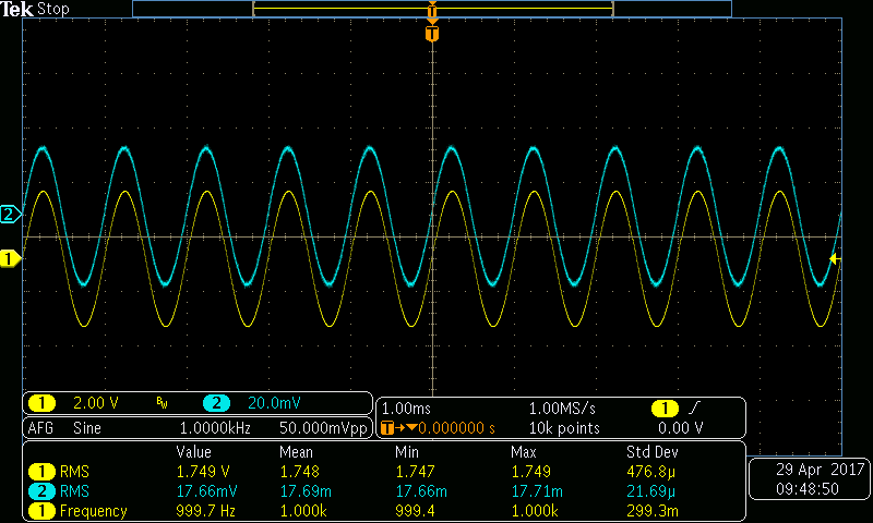
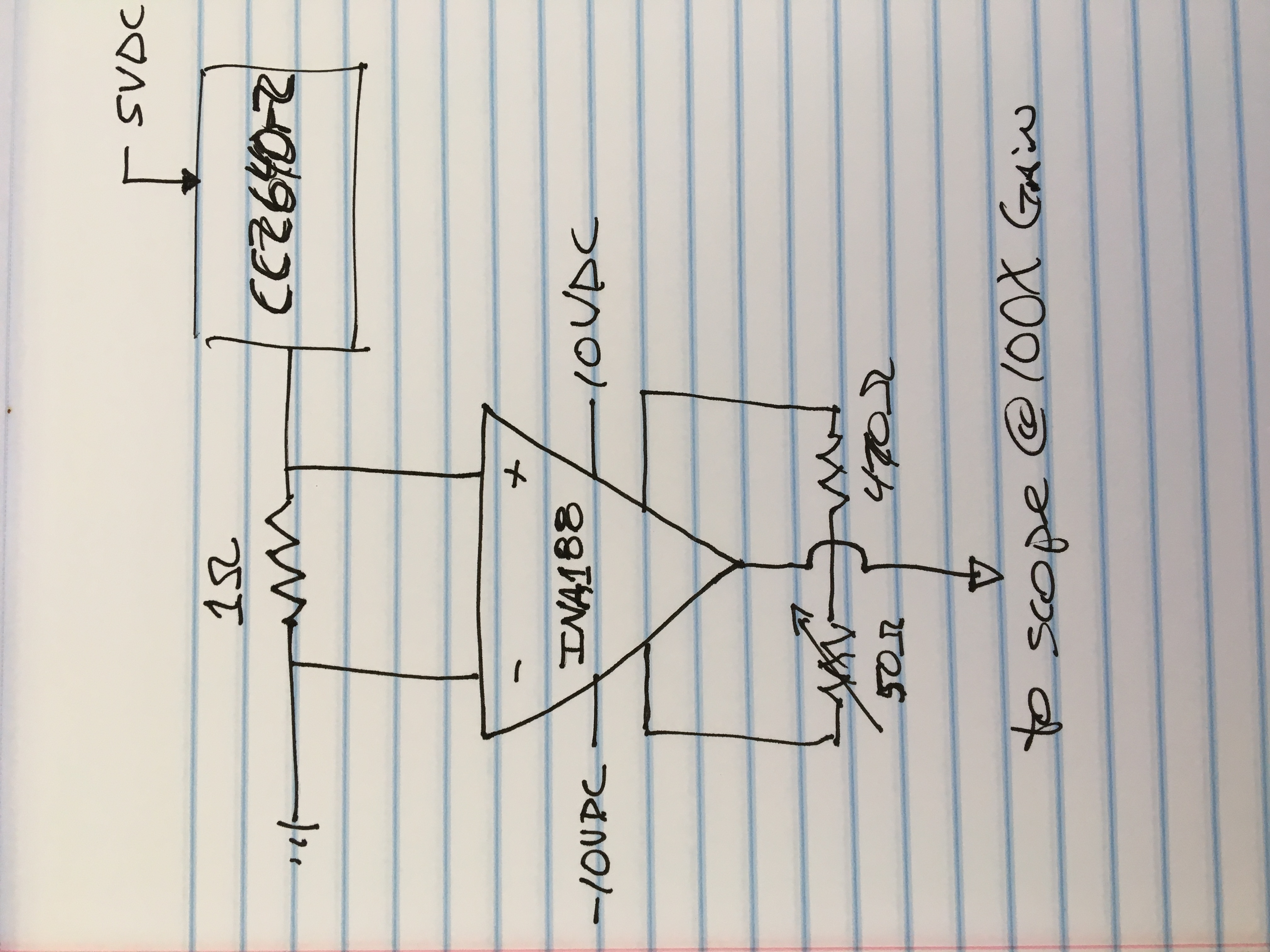
In an effort to measure current draw from my CC2640r2, I assembled the following circuit to get the voltage levels up to a point that they could be measured. I used a TI INA188 instrumentation amplifier for this purpose. Notice it uses a single gain resistor to set the gain. By using a single fixed resistor and trim pot I was able to dial in the amplifier gain to exactly 100 @ 1Khz. Also, notice that the inputs to amplifier are across a 1 ohm resistor. This allows me to measure voltage across the shunt resistor. The CC2640r2 LaunchPad is powered from an external bench power supply connected to the 5VDC pin on the board. The circuit shown below is inserted in the circuit return path as shown. Of course there are instruments that will do all of this for you, but they're expensive. This configuration allows measurement of the parameters needed to make a pretty accurate estimate of current draw and thus battery life.
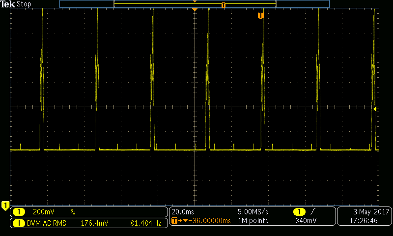
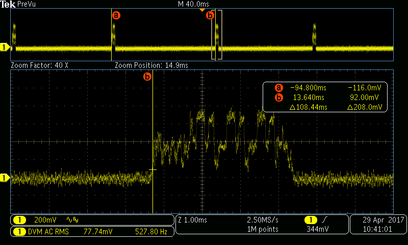
This allowed me to make some measurements of current draw as a function of time with sufficiently high resolution on the scope to capture individual BTLE connection events. Following shows the device in advertising mode. Notice that the advertising period is set to 100mS. The RMS voltage is 0.8mA (remember I'm measuring through a 100X amplifier so 77.7mV measured is actually 0.8mV)
Following is a measurement of current while the CC2640r2 is connected via BTLE to a phone. Notice that since the connection events occur closer together ~30mS this condition draws more RMS current.

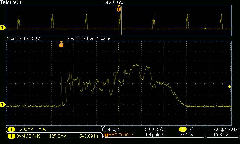
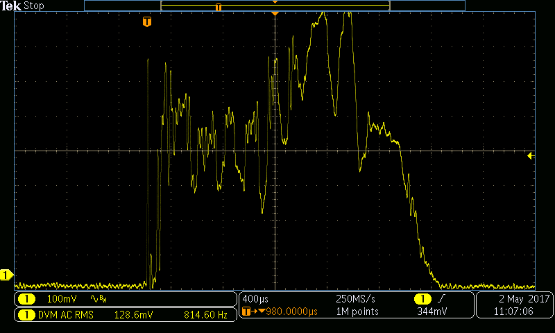
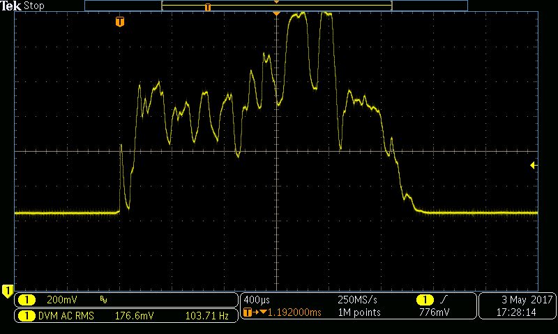
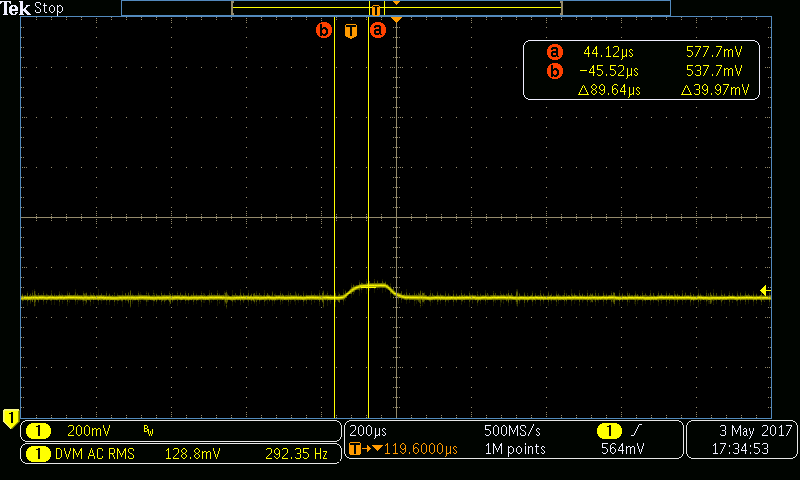
The other nice thing about using the scope to look at the current draw is that the individual connection events can be measured.