


Other Parts Discussed in Thread: CC1350
Hello all,
I am working on my custom board for CC2640R2F, I am having some problem regarding to programming the chip.
I am using CC2640R2F LaunchPad to program my custom board. The programming interface connection is as followed.
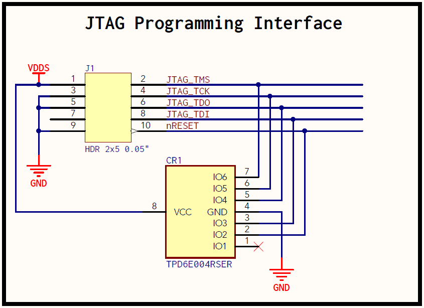
TMS is connected to Pin 24
TCK is connected to Pin 25
TDO is connected to Pin 26
TDI is connected to Pin 27
The diode TPD6E004RSER somehow caused me the problem (Error XBAL something as I recalled) of connecting to the board so I took it out. So now the pins are connected directly to the board without going through the diodes, I wonder if this would cause some issues ultimately?
Now come to the weird part. I cannot use Code Composer Studio (v8) to debug the board at all. Here is the error message when I try to debug the board from CCS

However, I can use Smart RF Flash Programmer 2 to load the firmware to the board, but there is a catch. 95% of the time, Smart RF Programmer 2 crashed when it is in the verification step, then I power cycle the board and the program is loaded into the chip and it works perfectly. The other 5%, The verification went through successfully and the board would be working as expected.
I really don't know what is the problem here. I ultimately want to use CCS8 to debug the board as my next revision will have a motor driver with MOSFETs on it so I want to be able to adjust the PWM setting, without the ability to step through the code, I can see days of nightmare ahead.
I am not sure what type of JTAG (4-wire JTAG, 2-wire cJTAG or 4-wire cJTAG) is being used to program the board if I use the launchpad as the programmer route. When I un-tick the option of "use 2-pin cJTAG" in Smart RF Programmer 2, it would hang and not going through the programming sequence.
Can you guys give me some suggestion of how you connect your JTAG programming interface with the chip and what tool do you use to successfully debug/program the custom board?
FYI, here is the picture of the setup

Much appreciate!
Alex

