


Other Parts Discussed in Thread: MSP430FR5969
Hello,
I am trying to communicate with MSP430FR5969 Launchpad from CC2650 Launchpad using I2C. The CC2650 Launchpad configured as Master and send 5 bytes of data one by one. The MSP430FR5969 Launchpad configured as slave to receive data. Both the code are compiles without errors. When I run the master sends 5 bytes but the data not received in slave.
I have checked the slave code using another MSP430FR5969 Launchpad configured as a master. The communication happen correctly and data from master received in slave. I don't understand why the communication not happen. Here with I have attached the source codes for all.
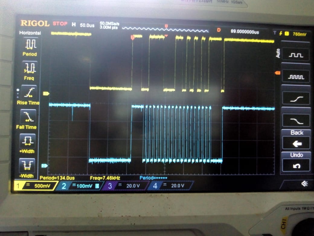
I have attached captured waveform of single byte I2C transmission for your reference.
Kindly help me to communicate between CC2650 Launchpad and MSP430Fr5969.
Thanks and Regards,
Murali M
/*
* Copyright (c) 2015-2016, Texas Instruments Incorporated
* All rights reserved.
*
* Redistribution and use in source and binary forms, with or without
* modification, are permitted provided that the following conditions
* are met:
*
* * Redistributions of source code must retain the above copyright
* notice, this list of conditions and the following disclaimer.
*
* * Redistributions in binary form must reproduce the above copyright
* notice, this list of conditions and the following disclaimer in the
* documentation and/or other materials provided with the distribution.
*
* * Neither the name of Texas Instruments Incorporated nor the names of
* its contributors may be used to endorse or promote products derived
* from this software without specific prior written permission.
*
* THIS SOFTWARE IS PROVIDED BY THE COPYRIGHT HOLDERS AND CONTRIBUTORS "AS IS"
* AND ANY EXPRESS OR IMPLIED WARRANTIES, INCLUDING, BUT NOT LIMITED TO,
* THE IMPLIED WARRANTIES OF MERCHANTABILITY AND FITNESS FOR A PARTICULAR
* PURPOSE ARE DISCLAIMED. IN NO EVENT SHALL THE COPYRIGHT OWNER OR
* CONTRIBUTORS BE LIABLE FOR ANY DIRECT, INDIRECT, INCIDENTAL, SPECIAL,
* EXEMPLARY, OR CONSEQUENTIAL DAMAGES (INCLUDING, BUT NOT LIMITED TO,
* PROCUREMENT OF SUBSTITUTE GOODS OR SERVICES; LOSS OF USE, DATA, OR PROFITS;
* OR BUSINESS INTERRUPTION) HOWEVER CAUSED AND ON ANY THEORY OF LIABILITY,
* WHETHER IN CONTRACT, STRICT LIABILITY, OR TORT (INCLUDING NEGLIGENCE OR
* OTHERWISE) ARISING IN ANY WAY OUT OF THE USE OF THIS SOFTWARE,
* EVEN IF ADVISED OF THE POSSIBILITY OF SUCH DAMAGE.
*/
/*
* ======== I2C_TX_TEST.c ========
*/
/* XDCtools Header files */
#include <xdc/std.h>
#include <xdc/runtime/System.h>
/* BIOS Header files */
#include <ti/sysbios/BIOS.h>
#include <ti/sysbios/knl/Clock.h>
#include <ti/sysbios/knl/Task.h>
/* TI-RTOS Header files */
#include <ti/drivers/PIN.h>
#include <ti/drivers/I2C.h>
/* Board Header files */
#include "Board.h"
#define TASKSTACKSIZE 768
Task_Struct task0Struct;
Char task0Stack[TASKSTACKSIZE];
/* Pin driver handle */
static PIN_Handle ledPinHandle;
static PIN_State ledPinState;
/*
* Application LED pin configuration table:
* - All LEDs board LEDs are off.
*/
//pin connections----DIO4 - SCL, DIO5 - SDA, 3V3- VCC, 3V3- RES, GND- DC
PIN_Config ledPinTable[] = {Board_LED0 | PIN_GPIO_OUTPUT_EN | PIN_GPIO_LOW | PIN_PUSHPULL | PIN_DRVSTR_MAX,
PIN_TERMINATE};
/*
* ======== taskFxn ========
* Toggle the Board_LED0. The Task_sleep is determined by arg0 which
* is configured for the heartBeat Task instance.
*/
uint8_t rxBuffer[1] = {0}; // Receive buffer
uint8_t txBuffer[1] = {0x01};//, 0x02};
uint8_t tx_data[5] = {0xAA, 0x55, 0x99, 0xAA, 0x99};
uint8_t rx_data[5] = {0};
bool transferDone = false;
I2C_Params params;
I2C_Handle handle; //handle which returned from i2c_opencall()
I2C_Transaction i2cTrans;
int i;
static void transferCallback(I2C_Handle handle, I2C_Transaction *transac, bool result)
{
// Set length bytes
if (result) {
transferDone = true;
}
}
static void taskFxn(UArg a0, UArg a1)
{
// Configure I2C parameters.
I2C_Params_init(¶ms);
params.transferMode = I2C_MODE_CALLBACK; //wait in queue mode untill transfer completes.
params.transferCallbackFxn = transferCallback;
params.bitRate = I2C_100kHz;
//while(1)
{
for(i = 0;i < 5; i++)
{
// Prepare data to send, send 0x00, 0x01, 0x02, ...0xFF, 0x00, 0x01...
handle = I2C_open(Board_I2C, ¶ms); //which i2c on board, set transfer mode, bit rate specified in parameters.
txBuffer[0] = tx_data[i];
// Initialize master I2C transaction structure
i2cTrans.writeCount = 1;
i2cTrans.writeBuf = txBuffer;//tx_data[i];
i2cTrans.readCount = 0;
i2cTrans.readBuf = rxBuffer;//rx_data[i];
i2cTrans.slaveAddress = 0x3C;
CPUdelay(40);
I2C_transfer(handle, &i2cTrans);
rx_data[i] = rxBuffer[0];
Task_sleep(1000/Clock_tickPeriod);
I2C_close(handle);
PIN_setOutputValue(ledPinHandle, Board_LED0,
!PIN_getOutputValue(Board_LED0));
}
}
}
//for sending command over i2c
/*
* ======== main ========
*/
int main(void)
{
Task_Params taskParams;
/* Call board init functions */
Board_initGeneral();
/* Open LED pins */
ledPinHandle = PIN_open(&ledPinState, ledPinTable);
/* Construct heartBeat Task thread */
Task_Params_init(&taskParams);
taskParams.arg0 = 1000000 / Clock_tickPeriod;
taskParams.stackSize = TASKSTACKSIZE;
taskParams.stack = &task0Stack;
Task_construct(&task0Struct, (Task_FuncPtr)taskFxn, &taskParams, NULL);
PIN_setOutputValue(ledPinHandle, Board_LED0, 1);
//reset the module
System_printf("Starting the example\nSystem provider is set to SysMin. "
"Halt the target to view any SysMin contents in ROV.\n");
/* SysMin will only print to the console when you call flush or exit */
System_flush();
/* Start BIOS */
BIOS_start();
return (0);
}
#include <msp430.h>

volatile unsigned char RXData[5];
//volatile unsigned char TXData=0xff;
//unsigned char write_flag = 0;
volatile unsigned int count;

int main(void)
{
  WDTCTL = WDTPW | WDTHOLD;

  // Configure GPIO
  P1SEL1 |= BIT6 | BIT7;                    // I2C pins

  // Disable the GPIO power-on default high-impedance mode to activate
  // previously configured port settings
  PM5CTL0 &= ~LOCKLPM5;

  // Configure USCI_B0 for I2C mode
  UCB0CTLW0 = UCSWRST;                      // Software reset enabled
  UCB0CTLW0 |= UCMODE_3 | UCSYNC;           // I2C mode, sync mode
  UCB0I2COA0 = 0x3C | UCOAEN;               // own address is 0x48 + enable
  UCB0CTLW0 &= ~UCSWRST;                    // clear reset register
  UCB0IE |= UCSTPIE;
  while(1)
  {
    	  //__delay_cycles(75);
          UCB0CTLW0 &= ~UCTR;
          UCB0IE &= ~UCTXIE0;
          //write_flag = 1;
          UCB0IE |= UCSTPIE | UCRXIE0; // | UCSTTIE;       // transmit,stop, receive, start interrupt enable
          __bis_SR_register(LPM0_bits | GIE);                    // interrupts
  }
}

#if defined(__TI_COMPILER_VERSION__) || defined(__IAR_SYSTEMS_ICC__)
#pragma vector = USCI_B0_VECTOR
__interrupt void USCI_B0_ISR(void)
#elif defined(__GNUC__)
void __attribute__ ((interrupt(USCI_B0_VECTOR))) USCI_B0_ISR (void)
#else
#error Compiler not supported!
#endif
{
  switch(__even_in_range(UCB0IV, USCI_I2C_UCBIT9IFG))
  {
    case USCI_NONE:          break;         // Vector 0: No interrupts
    case USCI_I2C_UCALIFG:   break;         // Vector 2: ALIFG
    case USCI_I2C_UCNACKIFG: break;         // Vector 4: NACKIFG
    case USCI_I2C_UCSTTIFG:                 // Vector 6: STTIFG
      break;
    case USCI_I2C_UCSTPIFG:                 // Vector 8: STPIFG
      UCB0IFG &= ~UCSTPIFG;                 // Clear stop condition flag
      count = 0;
      __bic_SR_register_on_exit(LPM0_bits);
      break;
    case USCI_I2C_UCRXIFG3:  break;         // Vector 10: RXIFG3
    case USCI_I2C_UCTXIFG3:  break;         // Vector 12: TXIFG3
    case USCI_I2C_UCRXIFG2:  break;         // Vector 14: RXIFG2
    case USCI_I2C_UCTXIFG2:  break;         // Vector 16: TXIFG2
    case USCI_I2C_UCRXIFG1:  break;         // Vector 18: RXIFG1
    case USCI_I2C_UCTXIFG1:  break;         // Vector 20: TXIFG1
    case USCI_I2C_UCRXIFG0:                 // Vector 22: RXIFG0
        RXData[count] = UCB0RXBUF;
        count++;
        //__bic_SR_register_on_exit(LPM0_bits);
        break;
    case USCI_I2C_UCTXIFG0:
        //__delay_cycles(100);
        //UCB0TXBUF = TXData;                 // Vector 24: TXIFG0
        //__bic_SR_register_on_exit(LPM0_bits);
      break;
    case USCI_I2C_UCBCNTIFG: break;         // Vector 26: BCNTIFG
    case USCI_I2C_UCCLTOIFG: break;         // Vector 28: clock low timeout
    case USCI_I2C_UCBIT9IFG: break;         // Vector 30: 9th bit
    default: break;
  }
}
#include <msp430.h>

volatile unsigned char TXData[5] = {0xAA, 0x99, 0x55, 0x11, 0xCC};
volatile unsigned char RXData = 0;
unsigned int cnt = 0;
int main(void)
{
  WDTCTL = WDTPW | WDTHOLD;

  // Configure GPIO
  P1OUT &= ~BIT0;                           // Clear P1.0 output latch
  P1DIR |= BIT0;                            // For LED
  P1SEL1 |= BIT6 | BIT7;                    // I2C pins

  // Disable the GPIO power-on default high-impedance mode to activate
  // previously configured port settings
  PM5CTL0 &= ~LOCKLPM5;

  // Configure USCI_B0 for I2C mode
  UCB0CTLW0 |= UCSWRST;                     // Software reset enabled
  UCB0CTLW0 |= UCMODE_3 | UCMST | UCSYNC;   // I2C mode, Master mode, sync
  UCB0CTLW1 |= UCASTP_2;                    // Automatic stop generated
                                            // after UCB0TBCNT is reached
  UCB0BRW = 0x0008;                         // baudrate = SMCLK / 8
  UCB0TBCNT = 0x0005;                       // number of bytes to be received
  UCB0I2CSA = 0x003C;                       // Slave address
  UCB0CTL1 &= ~UCSWRST;
  UCB0IE |= UCTXIE | UCNACKIE | UCBCNTIE;

  while (1)
  {
		  __delay_cycles(100);
		  while (UCB0CTL1 & UCTXSTP);             // Ensure stop condition got sent
		  UCB0CTLW0 |= UCTR;
		  UCB0IE &= ~UCRXIE;
		  UCB0IE |= UCTXIE | UCNACKIE | UCBCNTIE;
		  UCB0CTL1 |= UCTXSTT;                    // I2C start condition
	  __bis_SR_register(LPM0_bits | GIE);     // Enter LPM0 w/ interrupt
  }
}

#if defined(__TI_COMPILER_VERSION__) || defined(__IAR_SYSTEMS_ICC__)
#pragma vector = USCI_B0_VECTOR
__interrupt void USCI_B0_ISR(void)
#elif defined(__GNUC__)
void __attribute__ ((interrupt(USCI_B0_VECTOR))) USCI_B0_ISR (void)
#else
#error Compiler not supported!
#endif
{
  switch(__even_in_range(UCB0IV, USCI_I2C_UCBIT9IFG))
  {
    case USCI_NONE:          break;         // Vector 0: No interrupts
    case USCI_I2C_UCALIFG:   break;         // Vector 2: ALIFG
    case USCI_I2C_UCNACKIFG:                // Vector 4: NACKIFG
      UCB0CTL1 |= UCTXSTT;                  // I2C start condition
      break;
    case USCI_I2C_UCSTTIFG:  break;         // Vector 6: STTIFG
    case USCI_I2C_UCSTPIFG:  break;         // Vector 8: STPIFG
    case USCI_I2C_UCRXIFG3:  break;         // Vector 10: RXIFG3
    case USCI_I2C_UCTXIFG3:  break;         // Vector 12: TXIFG3
    case USCI_I2C_UCRXIFG2:  break;         // Vector 14: RXIFG2
    case USCI_I2C_UCTXIFG2:  break;         // Vector 16: TXIFG2
    case USCI_I2C_UCRXIFG1:  break;         // Vector 18: RXIFG1
    case USCI_I2C_UCTXIFG1:  break;         // Vector 20: TXIFG1
    case USCI_I2C_UCRXIFG0:                 // Vector 22: RXIFG0
      //RXData = UCB0RXBUF;                   // Get RX data
      //__bic_SR_register_on_exit(LPM0_bits); // Exit LPM0
      break;
    case USCI_I2C_UCTXIFG0:
    	UCB0TXBUF = TXData[cnt];
    	cnt++;
    	break;         // Vector 24: TXIFG0
    case USCI_I2C_UCBCNTIFG:                // Vector 26: BCNTIFG
      P1OUT ^= BIT0;                        // Toggle LED on P1.0
      cnt = 0;
      __bic_SR_register_on_exit(LPM0_bits);
      break;
    case USCI_I2C_UCCLTOIFG: break;         // Vector 28: clock low timeout
    case USCI_I2C_UCBIT9IFG: break;         // Vector 30: 9th bit
    default: break;
  }
}


