This thread has been locked.

If you have a related question, please click the "Ask a related question" button in the top right corner. The newly created question will be automatically linked to this question.

RTOS/CC2640: Registering two interrupt sources for one GPTimer

Part Number: CC2640

Tool/software: TI-RTOS

Hello,

I am trying to register two interrupt sources for one GPTimer of the CC2640.

First source: Positive edges on an defined pin (Therefore I am using the edge time up mode) 

Second source: Timeout of the timer (reaching the preset load value with   GPTimerCC26XX_setLoadValue(handle, 0xFFFFFF)  )  in periodic up mode

Independently from each other both sources trigger an interrupt, but if I try to combine them I do not get my desired result. 

Maybe a few questions ahead:

1. Is it possible to register more than one interrupt for one timer?

2. Is it even possible to use Timeout as an interrupt source in edge time up mode?

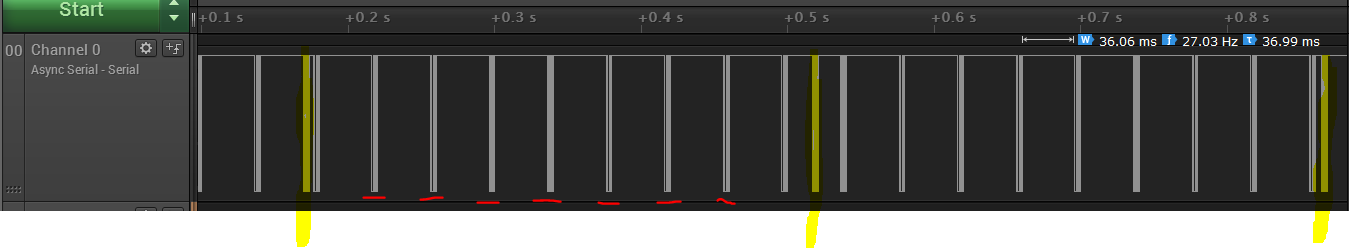
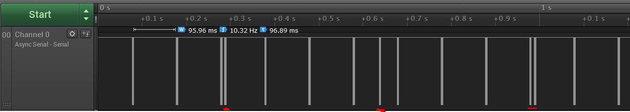
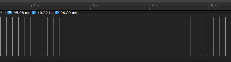
As a first try i used two 16 Bit Timers, where one works in edge time up mode (Timer A) and the other in periodic up mode (Timer B). The callback function of Timer A should reset Timer B, so that this one would never trigger an interrupt. With this implementation both timers are running correctly, but Timer B is not reset, which can be seen, because ruffly every 350 ms it triggers an interrupt, even though Timer A callback function is called several times in between. My try to reset Timer B in the callback function of Timer A looks like that:

GPTimerCC26XX_stop(hTimerB);
GPTimerCC26XX_start(hTimerB);

This was the approach using two timers, but more desirable would be a solution just using one timer. Therefore i worked with 

GPTimerCC26XX_enableInterrupt     and    GPTimerCC26XX_registerInterrupt     functions to add two interrupt sources to one timer. My tries were unsuccessfull though. 

So if anybody could provide advice or examples on one of my approaches to register two interrupt sources or successfully reset one timer i would be massively grateful. 

If there are even better ways i would be glad to hear them.

Kind regards

  • Add for my approach using two timers:

    Here (e2e.ti.com/.../420104 I read that SetLoadValue(..) should reset the timer, but as i mentioned Timer B generates an interrupt. So i tried this function, but can not see any difference to before:

    GPTimerCC26XX_stop(hTimerB);
    GPTimerCC26XX_setLoadValue(hTimerB, 0xFFFFFF);
    GPTimerCC26XX_start(hTimerB);

    In periodic up mode i imagine the timervalue to look like a saw tooth signal and the load value is the max value reachable. Is this a correct assumption?
  • Maybe a picture can clarify what i want:

    The yellow marked interrupt from Timer B occurs every 350 ms (LoadValue 0xFFFFFF with timer frequency 48 MHz), although the callback from Timer A is called often in between which should reset Timer B to zero again, so that it can never trigger an interrupt.

  • Hi Thauer,

    When the timer is configured in "counting up" mode, setting the load value would not result in a reset, you would simply change when to time-out. What you need to do when operating in counting up mode (as the GPTimer driver does) is to set the TAV register.

    There is no function for this in the driver, but you can try this instead:
    base + offset + register
    HWREG(bTimerB->hwAttrs->baseAddr + 4 + GPT_O_TAV) = 0;
  • Hi M-W,

    Thank you for your reply!

    Unfortunately if i implement my reset like that

    GPTimerCC26XX_stop(hTimerB);
    HWREG(hTimerB->hwAttrs->baseAddr + 4 + GPT_O_TAV) = 0;
    GPTimerCC26XX_start(hTimerB);

    i still get the same output as in the picture i provided.

    Did i miss something?
  • Hard to say without having the complete picture, could you provide a project I can look out and test out to see how everything is setup?
  • Here you can see the timer setup:

    // Timer A callback
    void timerCallback(GPTimerCC26XX_Handle handle, GPTimerCC26XX_IntMask interruptMask)
    {
        // Some other stuff
    
        GPTimerCC26XX_stop(hTimerB);
        HWREG(hTimerB->hwAttrs->baseAddr + 4 + GPT_O_TBV) = 0;
        GPTimerCC26XX_start(hTimerB);
    
    }
    
    
    // Timer B callback
    void ISR(GPTimerCC26XX_Handle handle, GPTimerCC26XX_IntMask interruptMask)
    {
        IntOn = 1;
    }
    
    // Timer Setup
    
    void InitHwTimer(void)
    {
        /* Timer 0A */
    
        PIN_Handle tPinHandle = PIN_open(&tPinState, pinTable);         // Indicator for interrupt pin
        if (tPinHandle == NULL)
        {
            while(1);
        }
    
        GPTimerCC26XX_Params params;
        GPTimerCC26XX_Params_init(&params);
        params.width          = GPT_CONFIG_16BIT;                      
        params.mode           = GPT_MODE_EDGE_TIME_UP;                  
        params.debugStallMode = GPTimerCC26XX_DEBUG_STALL_OFF;
        hTimerA = GPTimerCC26XX_open(Board_GPTIMER0A, &params);      
        if(hTimerA == NULL)
        {
            while(1);
        }
    
        GPTimerCC26XX_PinMux pinMux = GPTimerCC26XX_getPinMux(hTimerA);              
        PINCC26XX_setMux(tPinHandle, SENS_INT, pinMux);
    
        GPTimerCC26XX_setCaptureEdge(hTimerA, GPTimerCC26XX_POS_EDGE);               
        GPTimerCC26XX_setLoadValue(hTimerA, 0xFFFFFF);
    
        GPTimerCC26XX_registerInterrupt(hTimerA, timerCallback, GPT_INT_CAPTURE);
    
    
        /* Timer 0B */
    
        GPTimerCC26XX_Params paramsB;
        GPTimerCC26XX_Params_init(&paramsB);
        paramsB.width          = GPT_CONFIG_16BIT;
        paramsB.mode           = GPT_MODE_PERIODIC_UP;
        paramsB.debugStallMode = GPTimerCC26XX_DEBUG_STALL_OFF;
        hTimerB = GPTimerCC26XX_open(Board_GPTIMER0B, &paramsB);
        if(hTimerB == NULL)
        {
            while(1);
        }
    
        GPTimerCC26XX_setLoadValue(hTimerB, 0xFFFFFF);
    
        GPTimerCC26XX_registerInterrupt(hTimerB, ISR, GPT_INT_TIMEOUT);
    
        /* Starting the Timers */
    
        GPTimerCC26XX_start(hTimerA);
        GPTimerCC26XX_start(hTimerB);
    }

    In the main code InitHwTimer is called.

    Thanks again for your help!

  • Hi Thauer,

    This was a miss from my side, as you are trying to do this on the B timer, the register should be TBV and not TAV. Try swapping TAV out for TBV and see if that fixes it.
  • Hi M-W,

    I already tried this, but it had no effect.

    For now i am trying to set up my timer by writing straight into the registers without using the driver functions.

    For that reason, can you please explain the +4 in this line of code ?
    HWREG(hTimerB->hwAttrs->baseAddr + 4 + GPT_O_TAV) = 0;

    Thank you very much.
  • The "4" is offset, in this case it is simply extracted out of the GPTimer drivers LUT. I recommend you keep with the GPTimer and try to get that working as you will gain all the benefits of the TI-RTOS power management.

    I will try to look more into why you are not able to clear it.
  • Hi M-W,

    Thanks for the answer!

    Yeah, i concluded that it is smarter to stick with the GPTimers. At the moment i am trying to configure a Workaround using different threads, but when you have any further advice on resetting the timer value it would be greatly appreciated.

    Kind regards

  • Hi Thauer,

    So first of all, remove the + 4 offset i told you to use. This should only be used for some of the registers shared between the A and B timer, not for the TBV register. This should help you clear the register.

    This will help you with the clearing, unfortunately you can not clear the pre-scaler which means you would have to clear the register in a ~1.3 ms period to prevent the other timer. If clearing slower then this, you would at some point get a interrupt as the pre-scaler reaches 0xFF and the TBV register wraps (1.3ms ish at 16-bit 48MHz).

    You could "guard" against this interrupt by also looking for match interrupt flags as such:

    GPTimerCC26XX_registerInterrupt(hTimerB, ISR, GPT_INT_TIMEOUT | GPT_INT_MATCH);
    
    ...
    
    // Timer B callback
    void ISR(GPTimerCC26XX_Handle handle, GPTimerCC26XX_IntMask interruptMask)
    {
    if ((interruptMask & GPT_INT_TIMEOUT) && !(interruptMask & GPT_INT_MATCH)) {
    IntOn = 1;
    }
    }

  • Hi M-W,

    I tried something similar when working with on timer only, but even now with two timers it does not work.

    Below you can see the current code:

    void timerCallback(GPTimerCC26XX_Handle handle, GPTimerCC26XX_IntMask interruptMask)
    {
         // some other stuff
    
        GPTimerCC26XX_stop(hTimerB);
        HWREG(hTimerB->hwAttrs->baseAddr + GPT_O_TBV) = 0;
        GPTimerCC26XX_start(hTimerB);
    
        IntOn = 0;
    
    }
    
    void timerBCallback(GPTimerCC26XX_Handle handle, GPTimerCC26XX_IntMask interruptMask)
    {
        if ((interruptMask & GPT_INT_TIMEOUT) && !(interruptMask & GPT_INT_MATCH)) {
        IntOn = 1;
        }
    }
    
    void InitHwTimer(void)
    {
        /* Timer A */
    
        PIN_Handle tPinHandle = PIN_open(&tPinState, pinTable);         // Indicator for interrupt pin
        if (tPinHandle == NULL)
        {
            while(1);
        }
    
        GPTimerCC26XX_Params params;
        GPTimerCC26XX_Params_init(&params);
        params.width          = GPT_CONFIG_16BIT;                       // 16 Bit Timer ( +8 Bit with Prescaler)
        params.mode           = GPT_MODE_EDGE_TIME_UP;                  // Timer value when edge occurs is saved
        params.debugStallMode = GPTimerCC26XX_DEBUG_STALL_OFF;
        hTimerA = GPTimerCC26XX_open(Board_GPTIMER0A, &params);      // Indicator for HW Timer0A
        if(hTimerA == NULL)
        {
            while(1);
        }
    
    
        GPTimerCC26XX_PinMux pinMux = GPTimerCC26XX_getPinMux(hTimerA);              // Input pin which triggers the interrupt
        PINCC26XX_setMux(tPinHandle, Timer_pin, pinMux);
    
        GPTimerCC26XX_setCaptureEdge(hTimerA, GPTimerCC26XX_POS_EDGE);               // Interrupt on positive edge
        GPTimerCC26XX_setLoadValue(hTimerA, 0xFFFFFF);
    
        GPTimerCC26XX_registerInterrupt(hTimerA, timerCallback, GPT_INT_CAPTURE);
    
    
        /* Timer B */
    
        GPTimerCC26XX_Params paramsB;
        GPTimerCC26XX_Params_init(&paramsB);
        paramsB.width          = GPT_CONFIG_16BIT;
        paramsB.mode           = GPT_MODE_PERIODIC_UP;
        paramsB.debugStallMode = GPTimerCC26XX_DEBUG_STALL_OFF;
        hTimerB = GPTimerCC26XX_open(Board_GPTIMER0B, &paramsB);
        if(hTimerB == NULL)
        {
            while(1);
        }
    
        GPTimerCC26XX_setLoadValue(hTimerB, 0xFFFFFF);
    
        GPTimerCC26XX_registerInterrupt(hTimerB, timerBCallback, GPT_INT_TIMEOUT | GPT_INT_MATCH);
    
        /* Starting timers */
    
        GPTimerCC26XX_start(hTimerA);
        GPTimerCC26XX_start(hTimerB);
    }


    In the main code on IntOn == 1 an message is sent.

    As you can see, no reset of Timer B is done and it still triggers an interrupt every 350 ms.

    Did i miss something from your previous answer?

    Kind regards


  • Hi Thauer,

    Try setting the match value for the B Timer:

    GPTimerCC26XX_setMatchValue(hTimerB, 0xFFFFFF);
  • Now it stopped sending in between, but when no rising edges for Timer A are coming (no interrupt from Timer A)  and Timer B should be triggering an interrupt it does not.

  • I also wonder what timer is effected by setting the TBV register to zero, because i have 8 timers (or 4x16 Bit TimerA + 4x16 Bit Timer B) on the cc2640. Do the all use the same two registers? Maybe this is a guessing for the problem..
  • Hi Thauer,

    I'm sorry for this, the lack of a proper reset mechanism for 16-bit up-mode is annoying.

    I have an alternative solution you can try out that should be simpler for you but you will need to extend the GPTImer header file to add "Periodic down mode". If you go to the definition of "GPT_MODE_PERIODIC_UP" and in this enum add in a "GPT_MODE_PERIODIC_DOWN" mode:

    /* Periodic mode counting downwards */
    GPT_MODE_PERIODIC_DOWN = GPT_TAMR_TAMR_PERIODIC | GPT_TAMR_TACDIR_DOWN | \
    GPT_TAMR_TAMIE,

    After this, change the B timer to use this mode instead and remove the "MATCH" interrupt (we don't need it). In the timer A interrupt, instead of the writing TBV, simply update the load value:

    GPTimerCC26XX_setLoadValue(hTimerB, 0xFFFFFF);

    This should work a lot better then the up-mode approach. 

  • Regarding the effect of direct register access for the GPTimers, each of the four timers has unique base addresses so only the timer which base address you are using is effected (the name of the register for all four are the same).
  • Hi M-W,

    It worked! 

    Thank you very much for your patient and helpful assistance.

    This timer issue might be something to improve in future releases.

    Kind regards

    Thauer