This thread has been locked.

If you have a related question, please click the "Ask a related question" button in the top right corner. The newly created question will be automatically linked to this question.

LAUNCHXL-CC26X2R1: Touch Sense Gpio

Part Number: LAUNCHXL-CC26X2R1

Hello All,

I am using the cc26x2r1 Launchpad and I have connected 2 touch sense buttons to the GPIOs IOID_24 and IOID_25.  I enabled the Pins as follows :

IOID_24 | PIN_INPUT_EN | PIN_PULLUP,
IOD_25 | PIN_INPUT_EN | PIN_PULLUP,

Now, when I touch the touch buttons, the value is still reading as 1 (HIGH). I changed it to pulldown and it always reads 0. And when I give no pull it automatically alternates between 1s and 0s in a random manner.

I have just initialized the pins as gpios. Is there anything particular to be done when being used for touch sense ?

Regards,

Shyam

  • I would recommend looking at the cap sense example in Sensor Controller Studio.
  • Hi,
    Isn't Sensor Controller a different chip?
  • No. Start by looking at these: dev.ti.com/.../ to learn more about the Sensor Controller. Also see www.ti.com/.../swra578.pdf
  • Hi,
    I installed the Sensor Controller Studio. But was unable to find the capactitve sense example. Could you please tell me where it is located?
    Regards,
    Shyam
  • See under LaunchPad + ULP Sense Boosterpack under examples. It's called "Capacitive touch"
  • Hi,

    I got the example and tried to work it out. But I am sorry, I was not able to understand what was done in the example. Also I had seen the note in the example warning not to use the example as referende for actual production.

    Is there anyone who has done a touch button application of sorts that is rather easier to understand. It would be really helpful.

    I have a project that uses ble and an spi display and want to add 2 touch buttons to it. I have connected the touch buttons to gpios 24 and 25. Is there any simpler example for reference that I could use in my project? The capacitive touch sense example seems to be a bit complicated. 

    Also, could I be able to run the example on the Launchpad having no booster pack.

    Also I came across a few posts mentioning of a Capacitive Touch Data logger example. Is it the same? I could not find it either.

    Regards,

    Shyam

  • - To implement a cap touch button you need a PCB that is made for the purpose. For a prototype I would use the boosterpack, for a production version you need to add buttons on your own PCB. It's not straightforward to make a good button, one aspect is the shape/ size of the ground plane and a reference design should be used as a starting point.
    - The warning about using the code in production is due to:
    - The algorithm has not included all error checking that should be present in a final product. One example is that it has no test for a stuck at error (if something covering the sensor and that will be seen as a continuous press.
    - The algorithm is tuned for the buttons on the boosterpack. For your own buttons you may need to change the algorithm to be able to get a failure safe detection.
    - A touch sense algorithm basically have to be complex to not have false detects or failure to detect.
  • Hi,
    I have 2 touch buttons connected to gpios 24 and 25. Like I said in my previous post, I did not understand the code in the sensor controller studio. (If that is what you meant by the algorithm). Would you be able to provide any better documentation or maybe a simpler example I could be able to work with?

    Regards,
    Shyam
  • We have make a simple link academy training for this example that explains the code for the cap touch that will be out in the 2.40 version of the SDK. This SDK will be possible to download any day now, I see that at least the heading on the CC13x0 SDK is 2.40 now (the download is still 2.30), please keep an eye out for the newest SDK.
  • Would I have to download the latest sdk? Or will it be available under the support & training section?
    I will be keeping an eye on it. Hope it releases soon and becomese useful. I really do need to implement the touch buttons asap.
    I shall get back on this thread, once I go through the training. Thanks.
    Regards,
    Shyam
  • The latest I heard is that the SDK will be out on Friday. I'll see if I can upload part of the training here tomorrow.
  • Thanks TER. That would be great.

    Regards,
    Shyam
  • Hi, I too face the same issue . Please share if any updates on this
  • I have made screenshots of the part of the SLA that explain the code:

  • Hi, 

    Thank you for the explanation of the filter part of code.

    Apart from those, it would be helpful if you could explain about the below  points:

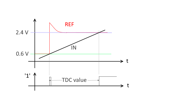
    1. In the sample code, the triggers set for tdc are compa high for both start and stop , but in the comment it is mentioned as ISRC reset release for start trigger.

    Which is the correct one to consider?

    // Enable the TDC with start trigger on ISRC reset release and stop trigger on COMPA

    tdcSetTriggers(TDC_STARTTRIG_COMPA_HIGH, TDC_STOPTRIG_COMPA_HIGH,1);

    2. In the sample code, we understand that a gpio signal is used as reference voltage to get a 0.6v as reference voltage and it is driven to 2.4v and then to a low voltage for a stop trigger of TDC.

    If we have to use an internal reference instead of external gpio , how can we achieve a high as start trigger and a high as stop trigger for TDC. Is that we have to enable compa without cap touch reference , if we use internal reference for compa input?

  • 1) I hope that the figure that is placed in the start of the SLA explains it:

    The measured capacitance will change as a finger touches the surface. It is this change that we can detect as touch. We can measure capacitance with the time-to-digital converter (TDC), combined with the ISRC (constant configurable current source) and COMPA peripherals which are used to control the TDC. To achieve good noise suppression, the reference start at 0.6 V by connecting a 400 kohm resistor to ground to the REF node (not shown in the figure). When the input reaches the first reference level, the comparator output goes high and the REF node is pulled to VDDS for 1 us to force the node high fast. The output of the comparator will then go low. At the same time the 400 kohm resistor is disconnected. Next the reference level is set to 2.4V, and the comparator will again go high when the input has reached this new reference level. At this point we can read out a 24-bit integer from the TDC, which provides the number of clock edges between the two positive edges of the comparator output. This value is a measure of the capacitance, in terms of the time constant of an RC circuit. We don't actually care about the absolute capacitance, but rather a relative measure

    The code always is the correct.

    2) In the first versions of the code the node was first set to 0 and then charged to 0.6 V but this solution is less immune against noise etc. 

  • Hi,
    Thank you for the clarification.

    For our project, we are short of GPIOs, so we cannot use external GPIO as reference for COMPA input. Is it possible to use Internal reference for COMPA reference input for capacitive touch.

    We have made the code as follows,

    --------------------------------------------------------------------------------------------------------------------------------------------
    compaEnableWithCapTouchRef();
    compaSelectIntRef(COMPA_REF_NONE);

    // Enable ISRC
    U16 current = BV_ISRC_CURR_2P0U | BV_ISRC_CURR_1P0U;
    isrcEnable(current);
    // Select 2 x 48 MHz from RCOSC_HF as TDC counter clock source
    tdcSetCntSource(TDC_CNTSRC_48M_RCOSC);

    // Enable the TDC with start trigger on ISRC reset release and stop trigger on COMPA
    tdcSetTriggers(TDC_STARTTRIG_ISRC_RELEASE, TDC_STOPTRIG_COMPA_HIGH,1);
    tdcEnable();

    // For each pin ...
    U16* pTdcSmplWindowPinBase = #state.pTdcSmplWindow;
    U16* pLowMeanWindowPinBase = #state.pLowMeanWindow;
    for (U16 n = 0; n < PIN_COUNT; n++) {

    // Select COMPA input/ISRC output
    compaSelectGpioInput(cfg.pAuxioAxdCapTouch[n]);

    // Prepare the TDC value window for inserting the new sample, start calculating
    // the mean value of the TDC value window
    U16* pTdcSmplItem = pTdcSmplWindowPinBase + (TDC_SMPL_WINDOW_SIZE - 2);
    U16 tdcSmplWindowMean = 0;
    while (pTdcSmplItem >= pTdcSmplWindowPinBase) {
    U16 tdcSmplItemValue = *(pTdcSmplItem++);
    *pTdcSmplItem = tdcSmplItemValue;
    pTdcSmplItem -= 2;
    tdcSmplWindowMean += tdcSmplItemValue;
    }

    // Prepare the TDC and trigger start of measurement
    tdcArm(TDC_START_ASYNC);
    isrcRelease(cfg.pAuxioAxdCapTouch[n]);

    // Wait for the COMPA output to go high, and then disconnect the internal 400 kOhm resistor.
    // This raises the COMPA referance voltage from 0.6 V to 2.4 V. Drive to VDDS for 1+ us to
    // ensure that the reference rises quickly, and then let it fall to 2.4 V.
    do {
    U16 compaValue;
    compaGetOutput(compaValue);
    } while (compaValue == 0);
    compaDisconnectCapTouchRefIntRes();
    compaSelectIntRef(COMPA_REF_VDDS);

    fwDelayInstrCycles(12);

    compaSelectIntRef(COMPA_REF_VSS);


    // Wait for the TDC stop trigger with 100 us timeout
    U16 isTdcDone;
    tdcWaitUs(100);
    tdcCheckDoneEv(isTdcDone);

    // Re-clamp the pin to ground
    isrcClamp(cfg.pAuxioAxdCapTouch[n]);

    // Reconnect the internal 400 kOhm resistor. This returns the COMPA reference voltage to 0.6 V.
    compaConnectCapTouchRefIntRes();

    // Check whether the TDC measurement actually finished, and then read and store the TDC value
    U16 tdcValueL;
    U16 tdcValueH;
    tdcGetValue(tdcValueH, tdcValueL);
    output.pTdcValueRaw[n] = tdcValueL;

    ---------------------------------------------------------------------------------------------------------------------------------------------------

    Can we use the internal reference instead of GPIO reference as above? Please let us know if any flaws in doing this.


    Thank You
  • It's something we haven't tested. It could be possible to use the DAC to do this but setting it has to be fast and with the correct timing. A colleague will look into this option if he has the time since this will save a pin.
  • You can test the attached that only use the internal reference and hence free up an extra DIO on CC13x2/ CC26x2. The signal will be slightly more noisy by using an internal signal vs an external reference. 

    cap_touch_ulpsense.scp