This thread has been locked.

If you have a related question, please click the "Ask a related question" button in the top right corner. The newly created question will be automatically linked to this question.

CCS/CC2650MODA: Porting from CC2640R2 launchpad to CC2650MODA

Part Number: CC2650MODA
Other Parts Discussed in Thread: CC2650, CC2640, SEGGER, BLE-STACK, CC2640R2F, SIMPLELINK-CC2640R2-SDK, CC2650STK, UNIFLASH

Tool/software: Code Composer Studio

Hi guys,

I wont to port my project from the cc2640r2 launchpad to the cc2650moda. I just use the launchpad to test my code and now, I need to use a custom board with ONLY the UART interface with the cc2650 module. 
In the launchpad, I use the ble5_simple_central_stack and a modified version of the ble5_simple_central_app (simplelink_cc2640r2_sdk_3_20_00_21). 
Reading in the forum (e2e.ti.com/.../530439 and in the various documents, I understand that the cc2640 and the cc2650 are compatibles.
Now, I need to modify the UART pins (in my new board, I use DIO_0 and DIO_1 as UART TX and UART RX, instead DIO_2 and DIO_3 in the launchpad), and all the other pins are defined as PIN_UNASSIGNED.
My question is: Do I have to change other things?
I mean, I don't use any other peripheral (as display, led and so on), but I need to keep the basic structure, for the pairing and connection management and other things.

I tried to compile and debug the code in the new module, but something goes wrong. Even if I don't get any errors, after debug (on CCSv10) it appears to be "blocked" (I can't click the paly button in ccs).

Other information:
I am able to use both the segger j-link (with a custom and verified interface board) and the launchpad to program my module, with the 4-pin JTAG (TMS,TCK,TDO and TDI).
The cc2650moda has the 5x5 package.
I've done all the simplelink academy examples for the launchpad and I was able to run project zero and the TIRTOS uart_echo example in the cc2650moda.

Thanks in advance.

Best regards,

Federico

  • Hi Frederico,

    I have assigned an expert to assist you with this.

    Best Regards,
    Alec

  • Hi Alec,
    any news?
    thanks
    Federico

  • Federico,

    Please accept my sincerest apologies. This thread was assigned to me while I was out, and the team lost visibility on it.

    I'm going to research the issue you reported and I will provide you an update tomorrow, 10/22.

    Thanks,

    Luis

  • CC2640R2 example and binary are not compatible to CC2650. For CC2650, you should use BLE-STACK - V2.2.5 (Support for CC2640/CC2650)

  • Thank you very much!

  • Hi Chen,

    I've rea some threads that link to this guide: dev.ti.com/.../custom-hardware.html
    In this guide, made for an old version of simplelink sdk, if I understand correctly, it says that it is possible to "adapt" the launchpad fw for different modules. However, it is also written that:

    "The following defines are supported by the SimpleLink CC2640R2 SDK and refer to a reference design (EM or LaunchPad) created by TI.

    By changing the define above, the application project will pull in a board file that is adopted for the TI reference designs or development kits with same name. Click the links above for more information on their respective TI reference designs.

    Note:
    The CC2640R2F is pin compatible with the CC2650 and CC2640 wireless MCUs in equivalent QFN package sizes, so the above reference designs can be used when designing with the CC2640R2F."

    but in the path of the simplelink that I am using, the only possible choice is that of CC2640R2_LAUNCHXL, even if in the "board" folder there are also the others listed.
    In addition, in the same guide, there is also written:

    "The board file for CC2640R2_LAUNCHXL is made for the 7x7 mm QFN package using differential RF front end and internal biasing. To convert this board file to use for other smaller device packages (5x5 mm and 4x4 mm QFN), the board file will need to be modified since limited number of IO pins are available in the smaller packages.

    It is recommended to start customizing board file(s) based on a reference design that is similar to your selected package type and RF configuration. For example a design for a 5x5 mm QFN package with a differential front end and external bias should use the CC2640R2DK_5XD board files as a reference."

    It is possible that with the new versions of simplelink it is no longer possible to carry out what is described in this guide, and perhaps with this statement I am connected to what you say?

    Thanks
    Federico

  • Federico,

    The first thing to notice is that while similar, the CC2640/50 and CC2640R2 are not the same.

    When we introduced the CC2640R2, we created a new SDK, which contains a new version of the BLE Stack, for the CC2640R2.

    You can see that difference very clearly in our BLE-STACK page. There you will see that the CC2640 and CC2650 use the software called "BLE-STACK-2-X", currently at version 2.2.5, released on August of 2020. In contrast, the CC2640R2 uses the software called "SIMPLELINK-CC2640R2-SDK", currently at version 4.30 and released on October of 2020.

    If you have an application to port from a CC2640R2 to a CC2650, my recommendation would be to start from an example project on the the BLE-STACK 2.2.5 for the CC2650. Then, you can use the PDF document "SWRU393_CC2640_BLE_Software_Developer's_Guide" included in your SDK, typically under "C:\ti\simplelink\ble_sdk_2_02_05_01\docs". In particular, chapter 10 - "Creating a Custom Bluetooth low energy Application" will help you adapt to your custom hardware. After that, you could implement / integrate / import the functionality from your baseline CC2640R2 application, although the BLE-related APIs may have changed. In particular, you may find useful this guide for porting from CC2640 to CC2640R2 (although you're going the other way around).

    Now, said all of that, the CC2650 and CC2640R2 do have in common the 32-bit Arm Cortex-M3, so it makes sense that they can execute same binary code, as you were able to run project zero from CC26040R2 on your CC2650. Their main difference is the ROM, as mentioned in the guide I provided above.

    I hope this helps.

    Happy coding,

    Luis

  • Federico,

    I noticed that you rejected the answer.

    What specific questions do you have?

    -Luis

  • Hi Luis,

    I don't know how I rejected your answer, I didn't read before; maybe I made a mistake and I'm sorry for this. Anyway, you're right, and now I'm tryng to run the simple_central example, included in C:\ti\simplelink\ble_sdk_2_02_05_02\examples\cc2650em\simple_central. About that, I've got another question:

    If I run the example without modification, compiling is ok, but when I try to debug it, CCS gives me an error, as follow:
    Cortex_M3_0: Failed Board Reset: (Error -717 @ 0x0) Required dynamic library jscserdesv3 could not be located. The library isn't on the search path. (Emulation package 9.2.0.00002)

    If I run the sensor tag example, included in C:\ti\simplelink\ble_sdk_2_02_05_02\examples\cc2650stk\sensortag, I am able to debug it.
    Another example that I am able to debug is the uart_echo (included in C:\ti\tirtos_cc13xx_cc26xx_2_21_01_08\examples\TI\CC2650DK_5XD\uartecho).

    Now, I think in the coming days I will be able to modify the cc2650 simple central example as I done for the cc2640 launchpad.

    Just for clarity, my goal is to use the simple_central example and add UART comunication, because I want to send by UART from another micro 3 kind of commands:
    1-connect
    2-send data (received from the uart from the micro) via BLE to another device
    3-disconnect
    When receiving data via BLE, I want "copy" this data and put it to the UART tx buffer to send it to the another micro.

    Thank you

    Federico

  • Can you take a picture to show me how you connect debugger to your CC2650MODA?

  • Hi Chen,
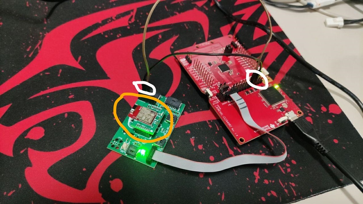
    this is my setup:
    - The red board is the cc2640r2 launchpad
    - The green one is a custom board that allows me to debug various devices. I am able to connect devices and program them through jtag.
    I can use also the segger j-link instead the launchpad.

    In the picture, circled in white there are the UART tx-rx lines, in yellow there is the cc2650moda.

    Let me know if you notice anything wrong with the setup.
    thanks in advance

    Federico

  • When you mention "I am able to connect devices and program them through jtag. I can use also the segger j-link instead the launchpad.", do you mean you can use Flash Programmer 2 or Uniflash with Jtag to program your CC2650 custom board? If yes, I see no reason why CCS cannot work.

  • Hi Chen,
    I never used Uniflash or Flash Programmer; I tried with the segger and I can correctly debug the example in the cc2650moda, using CCS, (in this case I need an external power supply, but this isn't a problem).
    I don't know what is the difference between these setups, but if using the segger I can debug the code, I don't dwell on this problem.
    Ty
    Federico

  • So, you don't have problem or issue now, right?

  • Yes, you're right...I click on the "this resolve my issue" button.
    Thanks