Part Number: BOOSTXL-AOA
Due to we want to plan to execute the AoA RF conformance Test(Bluetooth SIG RF Test), So we change to the BOOSTXL-AOA EVB to the conductor.(Change PCB antenna to SMA the connector) as below (with LAUNCHXL-CC26X2R1):

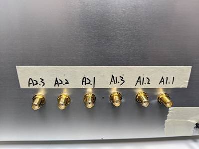
The BOOSTXL-AOA Evaluation board have Two antenna arrays with three 2.4 GHz dipole antennas on each, This mean that have 6 antenna connectors with SMA after re-work to conductive.
About above reason, I have some question as below:
1. According to the Bluetooth TEST SPEC, When need to perform the AoA Receiver test, All of the Antenna define on the Antenna need to connect to the RF Tester via combiner/splitter.
When we need to perform the AoA Receiver test, the correct connector method is?
(A) All of the antenna array(A1.1~ A1.3, A 2.1 ~ A2.3) total 6 connector, Connect to the RF Tester via combiner/splitter?
(B) Just choice one of antenna array in each side antenna(eg. A1.1 and A2.1) total 2 connector, Connect to the RF Tester via combiner/splitter?
(C) Another suggestion?

2. According to the Bluetooth TEST SPEC, The AoA Transmitter test is only using the single port that connects from EUT to the RF Tester.
But, There have a six SMA connector on the BOOSTXL-AOA EVB after re-work to conductive, which connector should connect to the RF-Tester?

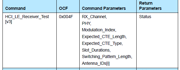
3. I found the host_test_app.hex in the SimpleLink CC13x2 26x2 SDK (4.30.00.54) recent that can respond the AoA HCI command & Event correctly, It means that support the AoA Test for Bluetooth RF Test uses HCI Command?