


Other Parts Discussed in Thread: MSP430F6779A, , CC2564, MSP430F5438, MSP430F6779
Hello TI/StoneStreet,
I am trying to interface CC2564MODN with MSP430F6779A and using the sample code provided in MSP430_EXP5438, SPPLEDemo_Lite.
I have changed the hardware configurations as per the MSP430 Hardware porting guidelines.
When I run the code I see that BSC_Initialize(HCI_DriverInformation, 0); is returning -4 which is BTPS_ERROR_HCI_INITIALIZATION_ERROR.
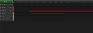
I have configured the UART port, CTS, RTS as per the guidelines. Also I can see slow clock on the pin.
Attached is the signal capture of UART and flow control pins.
/*****< HARDWARE.c >**********************************************************/
/* Copyright 2010 - 2014 Stonestreet One. */
/* All Rights Reserved. */
/* */
/* HARDWARE - Hardware API for MSP430 Experimentor Board */
/* */
/* Author: Tim Cook */
/* */
/*** MODIFICATION HISTORY ****************************************************/
/* */
/* mm/dd/yy F. Lastname Description of Modification */
/* -------- ----------- -----------------------------------------------*/
/* 07/07/10 Tim Cook Initial creation. */
/*****************************************************************************/
#include <msp430.h>
#include <string.h>
#include "HAL.h" /* MSP430 Hardware Abstraction API. */
#include "HRDWCFG.h" /* SS1 MSP430 Hardware Configuration Header.*/
#include "BTPSKRNL.h"
#define LED_WHITE BIT0 /* Status LED */ // LED_BLUE
#define LED_GREEN_B_R BIT1 /* Status LED */ // LED_GREEN_bottom_right
#define LED_GREEN_T_R BIT2 /* Status LED */ // LED_GREEN_top_right
#define LED_GREEN_T_L BIT3 /* Status LED */ // LED_GREEN_top_left
#define LED_GREEN_B_L BIT4 /* Status LED */ // LED_GREEN_bottom_left
#define LED_GREEN (LED_GREEN_T_L | LED_GREEN_T_R | LED_GREEN_B_R | LED_GREEN_B_L)
#define LED_GREEN_BOTTOM (LED_GREEN_B_R | LED_GREEN_B_L)
#define LED_ORANGE BIT5 /* Status LED */ // LED_ORANGE
#define MCU_P6_6_BIT BIT6 /* Not used */
#define MCU_P6_7_BIT BIT7 /* Not used */
#define P6DIR_INIT ( LED_WHITE | LED_GREEN_B_R | LED_GREEN_T_R | LED_GREEN_T_L | \
LED_GREEN_B_L | LED_ORANGE | MCU_P6_6_BIT | MCU_P6_7_BIT )
#define P6OUT_INIT (0)
#define BTPS_MSP430_DEFAULT_BAUD 115200L /* Default UART Baud Rate*/
/* used in baud rate */
/* given to this module */
/* is invalid. */
/* The following are some defines that we will define to be 0 if they*/
/* are not define in the device header. */
#ifndef XT1LFOFFG
#define XT1LFOFFG 0
#endif
#ifndef XT1HFOFFG
#define XT1HFOFFG 0
#endif
#ifndef XT2OFFG
#define XT2OFFG 0
#endif
/* Auxilary clock frequency */
#define ACLK_FREQUENCY_HZ ((unsigned int)32768)
/* Macro to stop the OS Scheduler. */
#define STOP_SCHEDULER() (TA1CTL &= (~(MC_3)))
/* Instruction to start the Scheduler Tick ISR. */
#define START_SCHEDULER() (TA1CTL |= MC_1)
/* The following structure represents the data that is stored to */
/* allow us to table drive the CPU setup for each of the Clock */
/* Frequencies that we allow. */
typedef struct _tagFrequency_Settings_t
{
unsigned char VCORE_Level;
unsigned int DCO_Multiplier;
} Frequency_Settings_t;
/* Internal Variables to this Module (Remember that all variables */
/* declared static are initialized to 0 automatically by the */
/* compiler as part of standard C/C++). */
/* The following variable is used to hold */
/* a system tick count for the Bluetopia */
/* No-OS stack. */
static volatile unsigned long MSP430Ticks;
/* The following function is provided to */
/* keep track of the number of peripherals*/
/* that have requested that the SMCLK stay*/
/* active. When this decrements to ZERO, */
/* the clock will be turned off. */
static volatile unsigned char ClockRequestedPeripherals;
/* The following is used to buffer */
/* characters read from the Debug UART. */
//static unsigned char RecvBuffer[BT_DEBUG_UART_RX_BUFFER_SIZE];
/* The following are used to track the */
/* Receive circular buffer. */
static unsigned int RxInIndex;
static unsigned int RxOutIndex;
//static unsigned int RxBytesFree = BT_DEBUG_UART_RX_BUFFER_SIZE;
/* If no buffer is specified, the this will result in a Blocking */
/* Write. */
#if BT_DEBUG_UART_TX_BUFFER_SIZE > 0
/* The following is used to buffer */
/* characters sent to the Debug UART. */
static unsigned char TransBuffer[BT_DEBUG_UART_TX_BUFFER_SIZE];
/* The following are used to track the */
/* Transmir circular buffer. */
static unsigned int TxInIndex;
static unsigned int TxOutIndex;
static unsigned int TxBytesFree = BT_DEBUG_UART_TX_BUFFER_SIZE;
#endif
/* The following represents the table that we use to table drive the */
/* CPU Frequency setup. */
static BTPSCONST Frequency_Settings_t Frequency_Settings[] =
{
{PMMCOREV_0, 244}, /* cf8MHZ_t. */
{PMMCOREV_1, 488}, /* cf16MHZ_t. */
{PMMCOREV_2, 610}, /* cf20MHZ_t. */
{PMMCOREV_3, 675} /* cf22.1184MHZ_t. */
};
/* External functions called by this module. These are neccessary */
/* for UART operation and reside in HCITRANS.c */
/* Called upon reception of a CTS Interrupt. Must toggle Interrupt */
/* Edge Polarity and flag Tx Flow Enabled State. */
extern int CtsInterrupt(void);
/* Local Function Prototypes. */
static Boolean_t DetermineProcessorType(void);
static void ConfigureBoardDefaults(void);
static void ConfigureLEDs(void);
static void ToggleLED(int LEDID);
static void SetLED(int LED_ID, int State);
static void ConfigureTimer(void);
static unsigned char IncrementVCORE(unsigned char Level);
static unsigned char DecrementVCORE(unsigned char Level);
static void ConfigureVCore(unsigned char Level);
static void StartCrystalOscillator(void);
static void SetSystemClock(Cpu_Frequency_t CPU_Frequency);
/* The following function is responsible for determining if we are */
/* running on the MSP430F5438 or the MSP430F5438A processor. This */
/* function returns TRUE if we are on the MSP430F5438A or FALSE */
/* otherwise. */
static Boolean_t DetermineProcessorType(void)
{
Boolean_t ret_val = FALSE;
/* Read the TLV descriptors to determine the device type. */
// if ((*((char *)0x1A04) == 0x05) && (*((char *)0x1A05) == 0x80))
ret_val = TRUE;
return(ret_val);
}
/* The following function is used to configure all unused pins to */
/* their board default values. */
static void ConfigureBoardDefaults(void)
{
P1DIR = P1DIR_INIT;
P1OUT = P1OUT_INIT;
P1SEL0 = P1SEL0_INIT;
P1SEL1 = P1SEL1_INIT;
P2DIR = P2DIR_INIT;
P2OUT = P2OUT_INIT;
P2SEL0 = P2SEL0_INIT;
P3DIR = P3DIR_INIT;
P3OUT = P3OUT_INIT;
P3SEL0 = P3SEL0_INIT;
P4DIR = P4DIR_INIT;
P4OUT = P4OUT_INIT;
P4SEL0 = 0x00;
P5DIR = P5DIR_INIT;
P5OUT = P5OUT_INIT;
P5SEL0 = 0x00;
P6DIR = P6DIR_INIT;
P6OUT = P6OUT_INIT;
P6SEL0 = 0x00;
P7DIR = P7DIR_INIT;
P7OUT = P7OUT_INIT;
P7SEL0 = 0x00;
P8DIR = P8DIR_INIT;
P8OUT = P8OUT_INIT;
P8SEL0 = 0x00;
PJOUT = 0;
PJDIR = 0xFF;
}
/* The following function is used to configure the board LEDs. */
static void ConfigureLEDs(void)
{
P6DIR = P6DIR_INIT;
P6OUT = P6OUT_INIT;
P6SEL0 = 0x00;
//P6SEL &= ~(BIT0 | BIT1);
//P6DIR |= (BIT0 | BIT1);
}
/* The following function is a utility function used to toggle an */
/* LED. */
static void ToggleLED(int LEDID)
{
if(P6OUT & BIT1)
{
P6OUT &= ~BIT1;
P6OUT |= BIT0;
}
else
{
P6OUT |= BIT1;
P6OUT &= ~BIT0;
}
}
/* The following function is a utility function that is used to set */
/* the state of a specified LED. */
static void SetLED(int LED_ID, int State)
{
Byte_t Mask;
if(LED_ID)
Mask = BIT1;
else
Mask = BIT0;
if(State)
P6OUT |= Mask;
else
P6OUT &= ~Mask;
}
/* This function is called to configure the System Timer, i.e TA1. */
/* This timer is used for all system time scheduling. */
static void ConfigureTimer(void)
{
/* Ensure the timer is stopped. */
TA1CTL = 0;
/* Run the timer off of the ACLK. */
TA1CTL = TASSEL_1 | ID_0;
/* Clear everything to start with. */
TA1CTL |= TACLR;
/* Set the compare match value according to the tick rate we want. */
TA1CCR0 = ( ACLK_FREQUENCY_HZ / MSP430_TICK_RATE_HZ ) + 1;
/* Enable the interrupts. */
TA1CCTL0 = CCIE;
/* Start up clean. */
TA1CTL |= TACLR;
/* Up mode. */
TA1CTL |= TASSEL_1 | MC_1 | ID_0;
}
/* The following function is a utility function the is used to */
/* increment the VCore setting to the specified value. */
static unsigned char IncrementVCORE(unsigned char Level)
{
unsigned char Result;
unsigned char PMMRIE_backup;
unsigned char SVSMHCTL_backup;
unsigned char SVSMLCTL_backup;
/* The code flow for increasing the Vcore has been altered to work */
/* around the erratum FLASH37. Please refer to the Errata sheet to */
/* know if a specific device is affected DO NOT ALTER THIS FUNCTION */
/* Open PMM registers for write access. */
PMMCTL0_H = 0xA5;
/* Disable dedicated Interrupts and backup all registers. */
PMMRIE_backup = PMMRIE;
PMMRIE &= ~(SVMHVLRPE | SVSHPE | SVMLVLRPE | SVSLPE | SVMHVLRIE | SVMHIE | SVSMHDLYIE | SVMLVLRIE | SVMLIE | SVSMLDLYIE );
SVSMHCTL_backup = SVSMHCTL;
SVSMLCTL_backup = SVSMLCTL;
/* Clear flags. */
PMMIFG = 0;
/* Set SVM highside to new level and check if a VCore increase is */
/* possible. */
SVSMHCTL = SVMHE | SVSHE | (SVSMHRRL0 * Level);
/* Wait until SVM highside is settled. */
while ((PMMIFG & SVSMHDLYIFG) == 0);
/* Clear flag. */
PMMIFG &= ~SVSMHDLYIFG;
/* Check if a VCore increase is possible. */
if((PMMIFG & SVMHIFG) == SVMHIFG)
{
/* Vcc is too low for a Vcore increase so we will recover the */
/* previous settings */
PMMIFG &= ~SVSMHDLYIFG;
SVSMHCTL = SVSMHCTL_backup;
/* Wait until SVM highside is settled. */
while ((PMMIFG & SVSMHDLYIFG) == 0)
;
/* Return that the value was not set. */
Result = 1;
}
else
{
/* Set also SVS highside to new level Vcc is high enough for a */
/* Vcore increase */
SVSMHCTL |= (SVSHRVL0 * Level);
/* Wait until SVM highside is settled. */
while ((PMMIFG & SVSMHDLYIFG) == 0)
;
/* Clear flags. */
PMMIFG &= ~SVSMHDLYIFG;
/* Set VCore to new level. */
PMMCTL0_L = PMMCOREV0 * Level;
/* Set SVM, SVS low side to new level. */
SVSMLCTL = SVMLE | (SVSMLRRL0 * Level) | SVSLE | (SVSLRVL0 * Level);
/* Wait until SVM, SVS low side is settled. */
while ((PMMIFG & SVSMLDLYIFG) == 0)
;
/* Clear flag. */
PMMIFG &= ~SVSMLDLYIFG;
/* SVS, SVM core and high side are now set to protect for the new */
/* core level. Restore Low side settings Clear all other bits */
/* _except_ level settings */
SVSMLCTL &= (SVSLRVL0+SVSLRVL1+SVSMLRRL0+SVSMLRRL1+SVSMLRRL2);
/* Clear level settings in the backup register,keep all other */
/* bits. */
SVSMLCTL_backup &= ~(SVSLRVL0+SVSLRVL1+SVSMLRRL0+SVSMLRRL1+SVSMLRRL2);
/* Restore low-side SVS monitor settings. */
SVSMLCTL |= SVSMLCTL_backup;
/* Restore High side settings. Clear all other bits except level */
/* settings */
SVSMHCTL &= (SVSHRVL0+SVSHRVL1+SVSMHRRL0+SVSMHRRL1+SVSMHRRL2);
/* Clear level settings in the backup register,keep all other */
/* bits. */
SVSMHCTL_backup &= ~(SVSHRVL0+SVSHRVL1+SVSMHRRL0+SVSMHRRL1+SVSMHRRL2);
/* Restore backup. */
SVSMHCTL |= SVSMHCTL_backup;
/* Wait until high side, low side settled. */
while(((PMMIFG & SVSMLDLYIFG) == 0) && ((PMMIFG & SVSMHDLYIFG) == 0))
;
/* Return that the value was set. */
Result = 0;
}
/* Clear all Flags. */
PMMIFG &= ~(SVMHVLRIFG | SVMHIFG | SVSMHDLYIFG | SVMLVLRIFG | SVMLIFG | SVSMLDLYIFG);
/* Restore PMM interrupt enable register. */
PMMRIE = PMMRIE_backup;
/* Lock PMM registers for write access. */
PMMCTL0_H = 0x00;
return(Result);
}
/* The following function is a utility function the is used to */
/* decrement the VCore setting to the specified value. */
static unsigned char DecrementVCORE(unsigned char Level)
{
unsigned char Result;
unsigned char PMMRIE_backup;
unsigned char SVSMHCTL_backup;
unsigned char SVSMLCTL_backup;
/* The code flow for decreasing the Vcore has been altered to work */
/* around the erratum FLASH37. Please refer to the Errata sheet to */
/* know if a specific device is affected DO NOT ALTER THIS FUNCTION */
/* Open PMM registers for write access. */
PMMCTL0_H = 0xA5;
/* Disable dedicated Interrupts Backup all registers */
PMMRIE_backup = PMMRIE;
PMMRIE &= ~(SVMHVLRPE | SVSHPE | SVMLVLRPE | SVSLPE | SVMHVLRIE | SVMHIE | SVSMHDLYIE | SVMLVLRIE | SVMLIE | SVSMLDLYIE );
SVSMHCTL_backup = SVSMHCTL;
SVSMLCTL_backup = SVSMLCTL;
/* Clear flags. */
PMMIFG &= ~(SVMHIFG | SVSMHDLYIFG | SVMLIFG | SVSMLDLYIFG);
/* Set SVM, SVS high & low side to new settings in normal mode. */
SVSMHCTL = SVMHE | (SVSMHRRL0 * Level) | SVSHE | (SVSHRVL0 * Level);
SVSMLCTL = SVMLE | (SVSMLRRL0 * Level) | SVSLE | (SVSLRVL0 * Level);
/* Wait until SVM high side and SVM low side is settled. */
while (((PMMIFG & SVSMHDLYIFG) == 0) || ((PMMIFG & SVSMLDLYIFG) == 0))
;
/* Clear flags. */
PMMIFG &= ~(SVSMHDLYIFG + SVSMLDLYIFG);
/* SVS, SVM core and high side are now set to protect for the new */
/* core level. */
/* Set VCore to new level. */
PMMCTL0_L = PMMCOREV0 * Level;
/* Restore Low side settings Clear all other bits _except_ level */
/* settings */
SVSMLCTL &= (SVSLRVL0+SVSLRVL1+SVSMLRRL0+SVSMLRRL1+SVSMLRRL2);
/* Clear level settings in the backup register,keep all other bits. */
SVSMLCTL_backup &= ~(SVSLRVL0+SVSLRVL1+SVSMLRRL0+SVSMLRRL1+SVSMLRRL2);
/* Restore low-side SVS monitor settings. */
SVSMLCTL |= SVSMLCTL_backup;
/* Restore High side settings Clear all other bits except level */
/* settings */
SVSMHCTL &= (SVSHRVL0+SVSHRVL1+SVSMHRRL0+SVSMHRRL1+SVSMHRRL2);
/* Clear level settings in the backup register, keep all other bits. */
SVSMHCTL_backup &= ~(SVSHRVL0+SVSHRVL1+SVSMHRRL0+SVSMHRRL1+SVSMHRRL2);
/* Restore backup. */
SVSMHCTL |= SVSMHCTL_backup;
/* Wait until high side, low side settled. */
while (((PMMIFG & SVSMLDLYIFG) == 0) && ((PMMIFG & SVSMHDLYIFG) == 0))
;
/* Clear all Flags. */
PMMIFG &= ~(SVMHVLRIFG | SVMHIFG | SVSMHDLYIFG | SVMLVLRIFG | SVMLIFG | SVSMLDLYIFG);
/* Restore PMM interrupt enable register. */
PMMRIE = PMMRIE_backup;
/* Lock PMM registers for write access. */
PMMCTL0_H = 0x00;
/* Return success to the caller. */
Result = 0;
return(Result);
}
/* The following function is responsible for setting the PMM core */
/* voltage to the specified level. */
static void ConfigureVCore(unsigned char Level)
{
unsigned int ActualLevel;
unsigned int Status;
/* Set Mask for Max. level. */
Level &= PMMCOREV_3;
/* Get actual VCore. */
ActualLevel = (PMMCTL0 & PMMCOREV_3);
/* Step by step increase or decrease the VCore setting. */
Status = 0;
while (((Level != ActualLevel) && (Status == 0)) || (Level < ActualLevel))
{
if (Level > ActualLevel)
Status = IncrementVCORE(++ActualLevel);
else
Status = DecrementVCORE(--ActualLevel);
}
}
/* The following function is responsible for starting XT1 in the */
/* MSP430 that is used to source the internal FLL that drives the */
/* MCLK and SMCLK. */
static void StartCrystalOscillator(void)
{
uint16_t srRegisterState = __get_SR_register() & (1 << 6);
P1SEL0 = ACLK_OUT | MCLK_OUT;
/* Enable XT1 and disable XT2, drive strength set to low current consumption */
UCSCTL6 &= ~(1 << 0);
// Internal load cap
UCSCTL6 |= (3 << 2); // XCAP = 3
// Check for Oscillator Fault flags on XT1
// Note from Sec 5.2.12 of Users guide SLAU208M:
// The OFIFG oscillator-fault interrupt flag is set and latched at POR or
// when any oscillator fault (XT1LFOFFG, XT1HFOFFG, XT2OFFG, or DCOFFG) is
// detected. Once set, the fault bits remain set until reset in software,
// regardless if the fault condition no longer exists. If the user clears the
// fault bits and the fault condition still exists, the fault bits are
// automatically set, otherwise they remain cleared.
// Clear the flags once before starting; since doing this first time after
// POR
UCSCTL7 &= ~(1 << 1); // XT1LFOFFG = 0
// Loop until XT1 fault flag is cleared
while (UCSCTL7 & (1 << 1))
{
// Clear XT1 fault flags
UCSCTL7 &= ~(1 << 1);
SFRIFG1 &= ~(1 << 1);
}
/* Set the FLL reference source to XT1CLK. The FLL reference divider bits 2-0 are set
to 0, for divide by 1.
*/
UCSCTL3 = 0; // SELREF = XT1CLK, FLLREFDIV = /1
// set ACLK source to XT1CLK
UCSCTL4 = 0; // SELA = XT1CLK, SELS = XT1CLK, SELM = XT1CLK
/* DCO Initialization to 16 MHz */
// disable the FLL loop control loop
__bic_SR_register(SCG0);
UCSCTL0 = 0x1F00; // Set DCO to lowest Tap fDCO(4,31), DCOx=31, MODx=0
UCSCTL2 &= ~(0x03FFu); // Clear the FLLN (Multiplier) bits
UCSCTL2 = 488; // 16000000/32768 = 488
UCSCTL1 = (4 << 4); // DCORSEL = 4, DISMOD = 0
/* Wait for DCO to Settle */
UCSCTL7 &= ~(1 << 0); // DCOFFG = 0
while (UCSCTL7 & (1 << 0))
{
// Clear DCO fault flags
UCSCTL7 &= ~(1 << 0); // DCOFFG = 0
SFRIFG1 &= ~(1 << 1); // OFFIFG = 0
}
__bis_SR_register(srRegisterState);
/* This is part of system HW initialization and happens at the very beginning.Delay
as recommended in TI's reference driver lib
*/
__delay_cycles(10000);
/* Check for Oscillator flag on XT2 */
// Note from Sec 5.2.12 of Users guide SLAU208O:
// The OFIFG oscillator-fault interrupt flag is set and latched at POR or
// when any oscillator fault (XT1LFOFFG, XT1HFOFFG, XT2OFFG, or DCOFFG) is
// detected. Once set, the fault bits remain set until reset in software,
// regardless if the fault condition no longer exists. If the user clears the
// fault bits and the fault condition still exists, the fault bits are
// automatically set, otherwise they remain cleared.
// set both MCLK and SMCLK to DCOCLK as source, ACLK src is already set to XT1
UCSCTL4 |= (3 << 4) | (3 << 0);
// Clear the flags once before starting; since doing this first time after POR
// workaround for Errata UCS11 - XT1HFOFFG not supported by this MCU
UCSCTL7 &= ~((1 << 3) | (1 << 1) | (1 << 0)); // XT2OFFG = 0, XT1LFOFFG = 0, DCOFFG = 0
SFRIFG1 &= ~(1 << 1); // OFIFG = 0
while (SFRIFG1 & (1 << 1))
{
UCSCTL7 &= ~((1 << 3) | (1 << 1) | (1 << 0)); // XT2OFFG = 0, XT1LFOFFG = 0, DCOFFG = 0
SFRIFG1 &= ~(1 << 1); // OFIFG = 0
}
}
/* The following function is responsible for setting up the system */
/* clock at a specified frequency. */
static void SetSystemClock(Cpu_Frequency_t CPU_Frequency)
{
Boolean_t UseDCO;
unsigned int Ratio;
unsigned int DCODivBits;
unsigned long SystemFrequency;
volatile unsigned int Counter;
BTPSCONST Frequency_Settings_t *CPU_Settings;
/* Verify that the CPU Frequency enumerated type is valid, if it is */
/* not then we will force it to a default. */
if((CPU_Frequency != cf8MHZ_t) && (CPU_Frequency != cf16MHZ_t) && (CPU_Frequency != cf20MHZ_t) && (CPU_Frequency != cf25MHZ_t))
CPU_Frequency = cf16MHZ_t;
/* Do not allow improper settings (MSP430F5438 cannot run at 20MHz or*/
/* 25 MHz). */
if((!DetermineProcessorType()) && ((CPU_Frequency == cf20MHZ_t) || (CPU_Frequency == cf25MHZ_t)))
CPU_Frequency = cf16MHZ_t;
/* Get the CPU settings for the specified frequency. */
CPU_Settings = &Frequency_Settings[CPU_Frequency - cf8MHZ_t];
/* Configure the PMM core voltage. */
ConfigureVCore(CPU_Settings->VCORE_Level);
/* Get the ratio of the system frequency to the source clock. */
Ratio = CPU_Settings->DCO_Multiplier;
/* Use a divider of at least 2 in the FLL control loop. */
DCODivBits = FLLD__2;
/* Get the system frequency that is configured. */
SystemFrequency = HAL_GetSystemSpeed();
SystemFrequency /= 1000;
/* If the requested frequency is above 16MHz we will use DCO as the */
/* source of the system clocks, otherwise we will use DCOCLKDIV. */
if(SystemFrequency > 16000)
{
Ratio >>= 1;
UseDCO = TRUE;
}
else
{
SystemFrequency <<= 1;
UseDCO = FALSE;
}
/* While needed set next higher div level. */
while (Ratio > 512)
{
DCODivBits = DCODivBits + FLLD0;
Ratio >>= 1;
}
/* Disable the FLL. */
__bis_SR_register(SCG0);
/* Set DCO to lowest Tap. */
UCSCTL0 = 0x0000;
/* Reset FN bits. */
UCSCTL2 &= ~(0x03FF);
UCSCTL2 = (DCODivBits | (Ratio - 1));
/* Set the DCO Range. */
if(SystemFrequency <= 630)
{
/* Fsystem < 630KHz. */
UCSCTL1 = DCORSEL_0;
}
else if(SystemFrequency < 1250)
{
/* 0.63MHz < fsystem < 1.25MHz. */
UCSCTL1 = DCORSEL_1;
}
else if(SystemFrequency < 2500)
{
/* 1.25MHz < fsystem < 2.5MHz. */
UCSCTL1 = DCORSEL_2;
}
else if(SystemFrequency < 5000)
{
/* 2.5MHz < fsystem < 5MHz. */
UCSCTL1 = DCORSEL_3;
}
else if(SystemFrequency < 10000)
{
/* 5MHz < fsystem < 10MHz. */
UCSCTL1 = DCORSEL_4;
}
else if(SystemFrequency < 20000)
{
/* 10MHz < fsystem < 20MHz. */
UCSCTL1 = DCORSEL_5;
}
else if(SystemFrequency < 40000)
{
/* 20MHz < fsystem < 40MHz. */
UCSCTL1 = DCORSEL_6;
}
else
UCSCTL1 = DCORSEL_7;
/* Re-enable the FLL. */
__bic_SR_register(SCG0);
/* Loop until the DCO is stabilized. */
while(UCSCTL7 & DCOFFG)
{
/* Clear DCO Fault Flag. */
UCSCTL7 &= ~DCOFFG;
/* Clear OFIFG fault flag. */
SFRIFG1 &= ~OFIFG;
}
/* Enable the FLL control loop. */
__bic_SR_register(SCG0);
/* Based on the frequency we will use either DCO or DCOCLKDIV as the */
/* source of MCLK and SMCLK. */
if (UseDCO)
{
/* Select DCOCLK for MCLK and SMCLK. */
UCSCTL4 &= ~(SELM_7 | SELS_7);
UCSCTL4 |= (SELM__DCOCLK | SELS__DCOCLK);
}
else
{
/* Select DCOCLKDIV for MCLK and SMCLK. */
UCSCTL4 &= ~(SELM_7 | SELS_7);
UCSCTL4 |= (SELM__DCOCLKDIV | SELS__DCOCLKDIV);
}
/* Delay the appropriate amount of cycles for the clock to settle. */
Counter = Ratio * 32;
while (Counter--)
__delay_cycles(30);
}
/* The following function is provided to allow a mechanism of */
/* configuring the MSP430 pins to their default state for the sample.*/
void HAL_ConfigureHardware(void)
{
/* Configure the default board setup. */
ConfigureBoardDefaults();
/* Configure the LEDs for outputs */
ConfigureLEDs();
/* Call the MSP430F5438 Experimentor Board Hardware Abstraction Layer*/
/* to setup the system clock. */
StartCrystalOscillator();
SetSystemClock(BT_CPU_FREQ);
/* Configure the UART-USB Port for its default configuration */
//HAL_CommConfigure(BT_DEBUG_UART_BASE, BT_DEBUG_UART_BAUDRATE, 0);
//GPIOPinTypeUART(BT_DEBUG_UART_PIN_BASE, BT_DEBUG_UART_PIN_TX_MASK, BT_DEBUG_UART_PIN_RX_MASK);
/* Enable Debug UART Receive Interrupt. */
//UARTIntEnableReceive(BT_DEBUG_UART_BASE);
/* Configure the scheduler timer. */
ConfigureTimer();
}
/* * NOTE * The following are the allowed flags for the flags */
/* argument. */
/* 1. UART_CONFIG_WLEN_8, UART_CONFIG_WLEN_7 */
/* 2. UART_CONFIG_PAR_NONE,UART_CONFIG_PAR_ODD,UART_CONFIG_PAR_EVEN*/
/* 3. UART_CONFIG_STOP_ONE,UART_CONFIG_STOP_TWO */
/* The flags is a bitfield which may include one flag from */
/* each of the three rows above */
void HAL_CommConfigure(unsigned char *UartBase, unsigned long BaudRate, unsigned char Flags)
{
unsigned long Frequency;
unsigned int Divider;
/* Since we allow access to register clear any invalid flags. */
Flags &= (UART_CONFIG_PAR_EVEN | UART_CONFIG_WLEN_7 | UART_CONFIG_STOP_TWO);
/* set UCSWRST bit to hold UART module in reset while we configure */
/* it. */
HWREG8(UartBase + MSP430_UART_CTL1_OFFSET) = MSP430_UART_CTL1_SWRST;
/* Configure control register 0 by clearing and then setting the */
/* allowed user options we also ensure that UCSYNC = Asynchronous */
/* Mode, UCMODE = UART, UCMSB = LSB first and also ensure that the */
/* default 8N1 configuration is used if the flags argument is 0. */
HWREG8(UartBase + MSP430_UART_CTL0_OFFSET) = Flags;
/* UART peripheral erroneous characters cause interrupts break */
/* characters cause interrupts on reception */
HWREG8(UartBase + MSP430_UART_CTL1_OFFSET) |= (MSP430_UART_CTL1_RXIE | MSP430_UART_CTL1_BRKIE);
/* clear UCA status register */
HWREG8(UartBase + MSP430_UART_STAT_OFFSET) = 0x00;
/* clear interrupt flags */
HWREG8(UartBase + MSP430_UART_IFG_OFFSET) &= ~(MSP430_UART_TXIFG_mask | MSP430_UART_RXIFG_mask);
/* If the baud rate is not valid, use the default. */
if(!BaudRate)
BaudRate = BTPS_MSP430_DEFAULT_BAUD;
/* Use ACLK for Baud rates less than 9600 to allow us to still */
/* receive characters while in LPM3. */
if(BaudRate <= 9600)
{
HWREG8(UartBase + MSP430_UART_CTL1_OFFSET) |= MSP430_UART_CTL1_UCSSEL_ACLK_mask;
Frequency = ACLK_FREQUENCY_HZ;
}
else
{
HWREG8(UartBase + MSP430_UART_CTL1_OFFSET) |= MSP430_UART_CTL1_UCSSEL_SMCLK_mask;
Frequency = HAL_GetSystemSpeed();
}
/* Calculate the initial baud rate divisor. This value can be used */
/* for correct rounding for either the low frequency or oversampling */
/* calculations. */
Divider = (unsigned int)((Frequency * 16) / BaudRate);
/* If the divider will be less than 32, use the low frequency */
/* calculation, otherwise use oversampling. Note that the current */
/* divider value is 16 times the actual divider. */
if(Divider < (32 * 16))
{
/* For low frequency baud rates, first calculate the divider * 8, */
/* rounded to the nearest integer. The lower 3 bits of the result */
/* will be the fraction portion of the divider and the rest will */
/* be the integer portion of the divider. */
Divider = (Divider + 1) / 2;
HWREG16(UartBase + MSP430_UART_BRW_OFFSET) = Divider / 8;
HWREG8(UartBase + MSP430_UART_MCTL_OFFSET) = (Divider & 0x07) << MSP430_UART_MCTL_BRS_bit;
}
else
{
/* For oversamping mode, first calculate the divider * 16, rounded*/
/* to the nearest integer. The lower 4 bits of the result will be */
/* the fraction portion of the divider and the rest will be the */
/* integer portion of the divider. */
Divider = (Divider + 8) / 16;
HWREG16(UartBase + MSP430_UART_BRW_OFFSET) = Divider / 16;
HWREG8(UartBase + MSP430_UART_MCTL_OFFSET) = ((Divider & 0x0F) << MSP430_UART_MCTL_BRF_bit) | MSP430_UART_MCTL_UCOS16_mask;
}
/* now clear the UCA2 Software Reset bit */
HWREG8(UartBase + MSP430_UART_CTL1_OFFSET) &= (~(MSP430_UART_CTL1_SWRST));
}
/* Called to read from a UART port and returns the number of bytes */
/* read. */
int HAL_ConsoleRead(unsigned int Length, char *Buffer)
{
// int Processed = 0;
// int CopyLength;
// int MaxRead;
// int Count;
//
// /* Make sure the passed in parameters seem valid. */
// if((Buffer) && (Length))
// {
// /* Read the characters if neccessary. */
// Processed = 0;
// while((Length) && (RxBytesFree != BT_DEBUG_UART_RX_BUFFER_SIZE))
// {
// /* Determine the number of characters until the buffer wraps. */
// Count = BT_DEBUG_UART_RX_BUFFER_SIZE - RxBytesFree;
// MaxRead = BT_DEBUG_UART_RX_BUFFER_SIZE - RxOutIndex;
// CopyLength = (MaxRead < Count)?MaxRead:Count;
//
// /* Process the number of characters till the buffer wraps or */
// /* maximum number that we can store in the passed in buffer. */
// CopyLength = (Length < CopyLength)?Length:CopyLength;
//
// /* Copy the characters over. */
// BTPS_MemCopy(&Buffer[Processed], &RecvBuffer[RxOutIndex], CopyLength);
//
// /* Update the counts. */
// Processed += CopyLength;
// Length -= CopyLength;
// RxOutIndex += CopyLength;
//
// /* Handle the case where the out index wraps. */
// if(RxOutIndex >= BT_DEBUG_UART_RX_BUFFER_SIZE)
// RxOutIndex = 0;
//
// /* This is changed in an interrupt so we must protect this */
// /* section. */
// __disable_interrupt();
//
// RxBytesFree += CopyLength;
//
// __enable_interrupt();
// }
// }
//
// return(Processed);
}
/* This function writes a fixed size string to the UART port */
/* specified by UartBase. */
void HAL_ConsoleWrite(unsigned int Length, char *String)
{
//#if BT_DEBUG_UART_TX_BUFFER_SIZE
//
// unsigned int Count;
//
//#endif
//
// volatile int Flags;
//
// /* First make sure the parameters seem semi valid. */
// if((Length) && (String))
// {
// /* Loop and transmit all characters to the Debug UART. */
// while(Length)
// {
//#if BT_DEBUG_UART_TX_BUFFER_SIZE
//
// if(TxBytesFree)
// {
// /* Get the number of bytes till we reach the end of the */
// /* buffer. */
// Count = (BT_DEBUG_UART_TX_BUFFER_SIZE-TxInIndex);
//
// /* Limit this by the number of Byte that are available. */
// if(Count > TxBytesFree)
// Count = TxBytesFree;
//
// if(Count > Length)
// Count = Length;
//
// /* Copy as much data as we can. */
// BTPS_MemCopy(&TransBuffer[TxInIndex], String, Count);
//
// /* Adjust the number of Free Bytes. */
// Flags = (__get_interrupt_state() & GIE);
// __disable_interrupt();
//
// TxBytesFree -= Count;
//
// if(Flags)
// __enable_interrupt();
//
// /* Adjust the Index and Counts. */
// TxInIndex += Count;
// String += Count;
// Length -= Count;
// if(TxInIndex == BT_DEBUG_UART_TX_BUFFER_SIZE)
// TxInIndex = 0;
//
// /* Check to see if we need to prime the transmitter. */
// if(!UARTIntTransmitEnabled(BT_DEBUG_UART_BASE))
// {
// /* Send the next character out. */
// UARTTransmitBufferReg(BT_DEBUG_UART_BASE) = TransBuffer[TxOutIndex++];
//
// /* Decrement the number of characters that are in the */
// /* transmit buffer and adjust the out index. */
// TxBytesFree++;
// if(TxOutIndex == BT_DEBUG_UART_TX_BUFFER_SIZE)
// TxOutIndex = 0;
//
// UARTIntEnableTransmit(BT_DEBUG_UART_BASE);
// }
// }
//
//#else
//
// /* Loop until the TXBUF is empty. */
// while(!UARTTransmitBufferEmpty(BT_DEBUG_UART_BASE));
//
// /* Now that the TXBUF is empty send the character. */
// UARTTransmitBufferReg(BT_DEBUG_UART_BASE) = *String;
//
// String++;
// Length--;
//
//#endif
// }
// }
}
/* The following function is used to return the configured system */
/* clock speed in MHz. */
unsigned long HAL_GetSystemSpeed(void)
{
Cpu_Frequency_t Frequency;
/* Verify that the CPU Frequency enumerated type is valid, if it is */
/* not then we will force it to a default. */
if((BT_CPU_FREQ != cf8MHZ_t) && (BT_CPU_FREQ != cf16MHZ_t) && (BT_CPU_FREQ != cf20MHZ_t) && (BT_CPU_FREQ != cf25MHZ_t))
Frequency = cf16MHZ_t;
else
Frequency = BT_CPU_FREQ;
if((!DetermineProcessorType()) && ((Frequency == cf20MHZ_t) || (Frequency == cf25MHZ_t)))
return(((unsigned long)Frequency_Settings[cf16MHZ_t - cf8MHZ_t].DCO_Multiplier) * 32768L);
else
return(((unsigned long)Frequency_Settings[Frequency - cf8MHZ_t].DCO_Multiplier) * 32768L);
}
/* This function is called to get the system Tick Count. */
unsigned long HAL_GetTickCount(void)
{
return(MSP430Ticks);
}
/* The following Toggles an LED at a passed in blink rate. */
void HAL_LedToggle(int LED_ID)
{
ToggleLED(0);
}
/* The following function is used to set an LED to a specified state.*/
void HAL_SetLED(int LED_ID, int State)
{
SetLED(LED_ID, State);
}
/* The following function is called to enter LPM3 mode on the MSP */
/* with the OS Timer Tick Disabled. */
void HAL_LowPowerMode(unsigned char DisableLED)
{
/* Turn off Timer 1, which is used for the FreeRTOS and NoRTOS */
/* timers. The timer runs off of the Auxilary Clock (ACLK) thus */
/* without this the timer would continue to run, consuming power */
/* and waking up the processor every 1 ms. Enter a critical section */
/* to do so that we do get switched out by the OS in the middle of */
/* stopping the OS Scheduler. */
__disable_interrupt();
STOP_SCHEDULER();
/* Clear the count register. */
TA1R = 0;
__enable_interrupt();
/* Turn off the LEDs if requested. */
if(DisableLED)
{
SetLED(0, 0);
SetLED(1, 0);
}
/* Enter LPM3. */
LPM3;
/* Re-start the OS scheduler. */
START_SCHEDULER();
/* Set the interrupt trigger bit to trigger an interrupt. */
TA1CCTL0 |= 0x01;
}
/* The following function is called to enable the SMCLK Peripheral */
/* on the MSP430. */
/* * NOTE * This function should be called with interrupts disabled. */
void HAL_EnableSMCLK(unsigned char Peripheral)
{
/* Note, we will only disable SMCLK Request if the Baud Rate for the */
/* Debug Console is less than or equal to 9600 BAUD. */
#if BT_DEBUG_UART_BAUDRATE <= 9600
UCSCTL8 |= SMCLKREQEN;
ClockRequestedPeripherals |= Peripheral;
#endif
}
/* The following function is called to disable the SMCLK Peripheral */
/* on the MSP430. */
/* * NOTE * This function should be called with interrupts disabled. */
void HAL_DisableSMCLK(unsigned char Peripheral)
{
/* Note, we will only disable SMCLK Request if the Baud Rate for the */
/* Debug Console is less than or equal to 9600 BAUD. */
#if BT_DEBUG_UART_BAUDRATE <= 9600
ClockRequestedPeripherals &= ~Peripheral;
if(!ClockRequestedPeripherals)
UCSCTL8 &= ~SMCLKREQEN;
#endif
}
/* Timer A Get Tick Count Function for BTPSKRNL Timer A Interrupt. */
/* Included for Non-OS builds */
#pragma vector=TIMER1_A0_VECTOR
__interrupt void TIMER_INTERRUPT(void)
{
++MSP430Ticks;
/* Exit from LPM if necessary (this statement will have no effect if */
/* we are not currently in low power mode). */
LPM3_EXIT;
}
/* CTS Pin Interrupt. CtsInterrupt routine must change the polarity */
/* of the Cts Interrupt. */
#pragma vector=BT_UART_CTS_IV
__interrupt void CTS_ISR(void)
{
switch(BT_UART_CTS_IVR)
{
case BT_UART_CTS_INT_NUM:
if(CtsInterrupt())
{
/* Exit LPM3 on interrupt exit (RETI). */
LPM3_EXIT;
}
break;
}
}
Also sending you the hardware configuration files.
It would be great if you can have look at the files and suggest me if I am missing on something and also the reasons behind returning -4.
Thanks,
Justin John
