This thread has been locked.

If you have a related question, please click the "Ask a related question" button in the top right corner. The newly created question will be automatically linked to this question.

BOOSTXL-AOA: cannot switch to use different antennas when run IQ data collection

Part Number: BOOSTXL-AOA

Greetings,

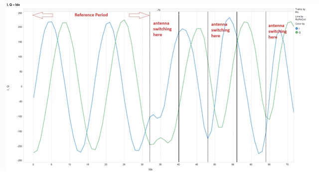
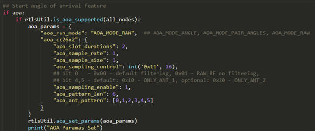
As I upgrade the SDK from 3.40 to newest version 4.40, now I can get raw IQ both from master and passive node, and they match the frame structure well. I notice the default aoa_params also changes: now the aoa_slot_duration =2 and aoa_sampling_control is int(‘0x11’,16), which I assume there is antenna switching. But I did not see any antenna idx change in any .csv files, the idx is always 1.

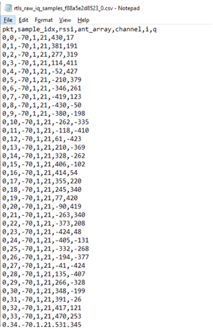
How can we enable antenna switching, and we can see antenna idx changes in the .csv file.  

Btw, what does the idx 1 or 2 in .csv file, does it mean  antenna 1-1 and 1-2( 2nd array of 1st row ULA), or it simply mean 1st ULA and 2nd ULA ?

Best.

Jet

  • Hi Jet,

    Which board are you running the RTLS master off of? Does the log from the RTLS passive also show the same?

  • I think `rtls_aoa_iq_with_rtls_util_export_into_csv.py ` running on both master and passive node. The python code save into 2 .csv files, one for master and one for passive. I dont see antenna change in any of the .csv files.

  • Hi,

    The results you have shared show that the antenna array used is always the first one. This is expected. Based on the way you are configuring the example through the Python script, I guess this information should be ignored.

    Actually, each CTE is sampled using the 6 antennas of the BOOSTXL-AOA (cf. aoa_pattern_len and aoa_ant_pattern). It means every time you are using both antenna arrays - so this information is basically useless.

    The antenna array id is supposed to tell which antenna array has been used to sample the CTE. The antenna used for a specific IQ sample can be found based on the configuration use as shown here.

    As a side note, if you wish to switch antenna array for each CTE reception, you need to:

    1. Set aoa_pattern_len and aoa_ant_pattern to use only 3 antennas each time
    2. Modify the embedded code to select a different antenna array after the end of reception of each CTE (this has been discussed before on the forum)

    Regards,

  • thanks a lot.

    Now I have to do is modify the embedded code.

    Best 

    Jet

  • My take is the python code by default only allow one ULA  of 3 antenna -- although the antenna idx is alway 1 in .csv file, it is indeed doing switching ant1-1 => ant1-2 => ant1-3 => ant1-1 => ant1-2 => ant1-3 .... I can go ahead to carefully watch the switching in the plot as in [ref]

    Best 

    Jet

  • Hi,

    I am sorry, I don't understand if you are asking an additional question here.

    Please mark as resolved all your threads that do not need anymore our attention. This is important to keep our work effective.

    Thanks and regards,