


Other Parts Discussed in Thread: CC2510
Hi Sir,
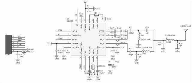
Our new project using CC2500 instead of CC2510 for the wireless design. The PCBA board adopts a two-layer design, and RF_N and RF_P pin come out as differential ports, followed by L1, L2, C13, C14 differential to single-ended balanced circuits. While the impedance matching in this part of the specification requires 80+j74, but our two-layer board cannot do the impedance matching. So we have a few questions about this.
1) Is it necessary to make a four-layer board to meet the requirements of 80+j74? Impedance matching can only be done by controlling the real part to the target of 80 ohms? Will it affect the actual performance?
2) Can this part of the balanced circuit be tested normally when the impedance matching of the two-layer board is not done? If so, is it tested with a network analyzer? Or it must be adjusted to 80+J74 to be considered OK?
The schematic is as follows:
Thanks,
Best Regards
