This thread has been locked.

If you have a related question, please click the "Ask a related question" button in the top right corner. The newly created question will be automatically linked to this question.

CC1352P: I2C intermittently stops reading sensor

Part Number: CC1352P
Other Parts Discussed in Thread: SYSCONFIG, LPSTK-CC1352R, HDC2080

I've been chasing an I2C issue where I expect the cc1352p to read 6 bytes from one of our sensors.

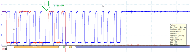
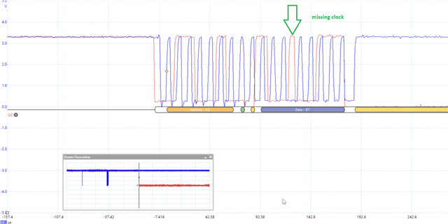
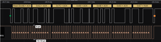
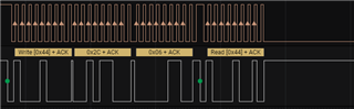
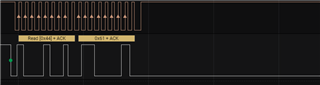
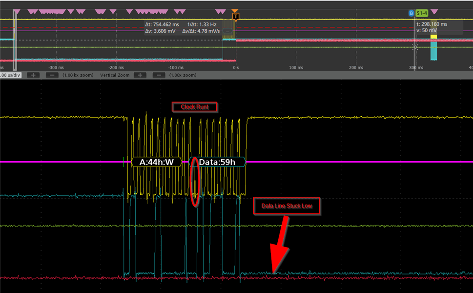
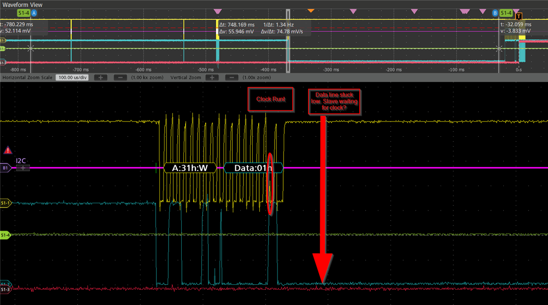
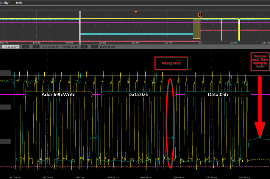
But it appears that the the read process stops driving the clock line after the first byte.

Here is a capture of the failure:

Notice that the data line is stuck low from this point forward.

I'm guessing the sensor is perpetually waiting for the rest of the clocks (5 more bytes) after the process has ack'd the first 2 bytes.

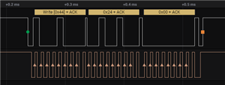
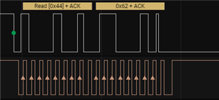
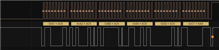
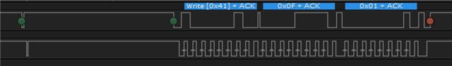
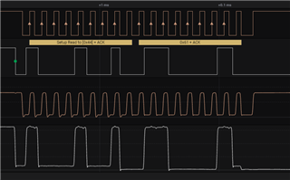
This is the capture of a successful occurrence:

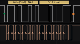
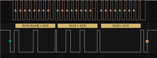
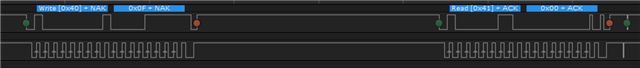
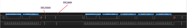
I hesitate to bring up this next observation, as it may be a red herring to the real problem, but when the read frame above immediately follows the following block, it is much more likely to fail.

But I want to stress that not following the following block doesn't make the problem go away, it is just greatly reduced.

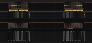
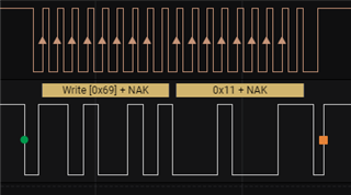
The above capture is a request to a different I2C device that is currently not present on the I2C bus.

The NACK following both attempts to talk to it are expected.

I'm am using SimpleLink_cc13x2_26x2_sdk_5_20_00_52

When stepping through the driver code, I get to the function "I2CSupport_primeTransfer", line 607:

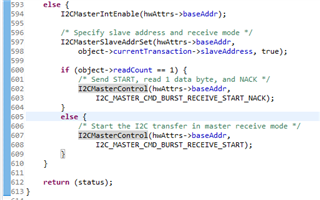
I have confirmed that the transaction object, specifically the "readCount" value is set to a value 6.

So the else case on line 607 seems to be the correct code-path for this case.

Another piece of information:

This is a project to port an existing product from the MSP432P401R (a processor you have decided to no longer support) to the CC1352P.
The I2C process was working just fine on the MSP432, so I'm wondering if there is something different that needs to be considered.

Also, I've looked through the errata, and did notice that there is a "CPUdelay(2)" in the I2CMasterControl function, looks like the "work-around" that is called out in the errata sheet:

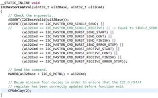
This doesn't sound like the same problem to me, but I thought I would mention it if it helps the conversation.

Thank you, and I'm looking forward to any help that can be provided...

  • I left out a detail for the 3rd capture above...

    Often times (but not always), those 2 frames will occur just before the first capture (when if fails)...
    The full frame would have the 3 bytes in the write command (0x69, 0x11, 0x03) when the device is present on the I2C bus.
    So the writeCount value is being set to 2 for that I2C_transferTimeout call.

  • Hi Cary

    To be able to help you further, there are several things that we need to know.

    Can you please share a complete example where you show how you configure the I2C driver and also the code you have written to transfer data on the I2C?

    It would also be useful is you could share information regarding the sensor you are communicating with, and that you share schematics showing how the CC1352 is connected to the sensor, and how you have configured the I2C in sysConfig.

    If I understand correctly, you have a solution working with the MSP432P401R. Which SDK are you using for this device, and can you share the code you have for this device to read from the sensors so that we can compare them with the code you have for CC1352?

    BR

    Siri

  • The MSP432 implementation was using simplelink_msp432p4_sdk_3_40_01_02.

    Next is the code library used by both the MSP432 and CC1352 implementations.
    We did notice that I2C driver function I2C_tranferTimeout seems to return more possible error codes in the new SDK, so we know there is a TODO to implement them. 

    i2c_multi.c
    /*
     * i2c_multi.c
     *
     *  Created on: May 5, 2020
     *      Author: derrick.simeon
     */
    
    /*
     * Includes
     */
    
    // Project-specific
    #include "AQ2.h"
    #include "msp432p401r_drivers/i2c_multi.h"
    #include "custom_assert.h"
    
    // C standard library
    #include <stdlib.h>
    #include <string.h>
    
    // SYS/BIOS
    #include <ti/sysbios/knl/Task.h>
    #include <ti/sysbios/knl/Semaphore.h>
    
    // TI-Drivers
    #include <ti/drivers/I2C.h>
    
    /*
     * Defines
     */
    
    #define SHT3X_I2C_ADDR          0x44
    #define STS3X_I2C_ADDR          0x4a
    #define CM110X_I2C_ADDR         0x31
    #define SGP30_I2C_ADDR          0x58
    #define MS5607_02BA03_I2C_ADDR  0x77
    #define CAT24C08_I2C_ADDR       0x54 // to 0x57
    
    #define TRANSFER_TIMEOUT_TICKS  100
    
    /*
     * Typedefs
     */
    
    /*
     * Local variables
     */
    
    I2C_Handle _m_i2cHandle;
    
    /*
     * Local functions
     */
    
    #ifdef I2C_MULTI_MODE_CALLBACK
    static void _callback(I2C_Handle handle, I2C_Transaction *transaction,
            bool transferStatus)
    {
    
    }
    #endif
    
    /*
     * Global functions
     */
    
    void I2C_MULTI_init(void)
    {
        static bool s_init = false;
        I2C_Params params;
    
        if(s_init)
            // Already initialized.
            return;
        else
            s_init = true;
    
        // One-time initialization of TI-Driver.
        I2C_init();
    
        // Initialize parameters.
        I2C_Params_init(&params);
    #ifdef I2C_MULTI_MODE_BLOCKING
        params.transferMode = I2C_MODE_BLOCKING;
        params.transferCallbackFxn = NULL;
    #else
        params.transferMode = I2C_MODE_CALLBACK;
        params.transferCallbackFxn = _callback;
    #endif
        params.custom = NULL;
        params.bitRate = I2C_100kHz;
    
        // Open for usage.
        _m_i2cHandle = I2C_open(I2C_MULTI, &params);
    
        ASSERT(_m_i2cHandle != NULL);
    }
    
    #ifdef I2C_MULTI_MODE_BLOCKING
    bool I2C_MULTI_read(uint8_t i2cAddr, void *pReadBuf, uint16_t nBytes)
    #else
    bool I2C_MULTI_read(uint8_t i2cAddr, void *pReadBuf, uint16_t nBytes)
    #endif
    {
        I2C_Transaction i2cTransaction = {0};
        bool success = false;
    
        i2cTransaction.slaveAddress = i2cAddr;
        i2cTransaction.writeBuf = NULL;
        i2cTransaction.writeCount = 0;
        i2cTransaction.readBuf = pReadBuf;
        i2cTransaction.readCount = nBytes;
    
        switch(I2C_transferTimeout(_m_i2cHandle, &i2cTransaction,
                TRANSFER_TIMEOUT_TICKS))
        {
            case I2C_STATUS_SUCCESS:
                success = true;
                break;
    
            case I2C_STATUS_ERROR:
            case I2C_STATUS_TIMEOUT:
                break;
    
            default:
                ASSERT_FAIL();
                break;
        }
    
        return success;
    }
    
    #ifdef I2C_MULTI_MODE_BLOCKING
    bool I2C_MULTI_write(uint8_t i2cAddr, const void *pWriteBuf, uint16_t nBytes)
    #else
    bool I2C_MULTI_write(uint8_t i2cAddr, const void *pWriteBuf, uint16_t nBytes)
    #endif
    {
        I2C_Transaction i2cTransaction = {0};
        bool success = false;
    
        i2cTransaction.slaveAddress = i2cAddr;
        i2cTransaction.writeBuf = (void *) pWriteBuf;
        i2cTransaction.writeCount = nBytes;
        i2cTransaction.readBuf = NULL;
        i2cTransaction.readCount = 0;
    
        switch(I2C_transferTimeout(_m_i2cHandle, &i2cTransaction,
                TRANSFER_TIMEOUT_TICKS))
        {
            case I2C_STATUS_SUCCESS:
                success = true;
                break;
    
            case I2C_STATUS_ERROR:
            case I2C_STATUS_TIMEOUT:
                break;
    
            default:
                ASSERT_FAIL();
                break;
        }
    
        return success;
    }
    
    #ifdef I2C_MULTI_MODE_BLOCKING
    bool I2C_MULTI_writeAndRead(uint8_t i2cAddr,
            const void *pWriteBuf, uint16_t nWriteBytes,
            void *pReadBuf, uint16_t nReadBytes)
    #else
    bool writeAndRead(uint8_t i2cAddr, const void *pWriteBuf, uint16_t nWriteBytes,
            void *pReadBuf, uint16_t nReadBytes)
    #endif
    {
        I2C_Transaction i2cTransaction = {0};
        bool success = false;
    
        i2cTransaction.slaveAddress = i2cAddr;
        i2cTransaction.writeBuf = (void *) pWriteBuf;
        i2cTransaction.writeCount = nWriteBytes;
        i2cTransaction.readBuf = pReadBuf;
        i2cTransaction.readCount = nReadBytes;
    
        switch(I2C_transferTimeout(_m_i2cHandle, &i2cTransaction,
                TRANSFER_TIMEOUT_TICKS))
        {
            case I2C_STATUS_SUCCESS:
                success = true;
                break;
    
            case I2C_STATUS_ERROR:
            case I2C_STATUS_TIMEOUT:
                break;
    
            default:
                ASSERT_FAIL();
                break;
        }
    
        return success;
    }
    

    Notice that the driver is initialized in blocking mode, and the I2C bus runs at 100k

    The 2 sensors that were captured in the images from my orignal post are the Sensiron SHT3x (first and second images, at I2C address 0x44), and the SPS30 (third image, at I2C address 0x69)

    The following function is called every 500ms to facilitate a "start measurement" during one cycle, and then a "get measurement" on the second:

    extern void SENSIRION_getSHT3XMeasurement(Sensirion_Sensor_t *pSensor,
            Temp_Msrmnt_t *pTmeas, RH_Msrmnt_t *pRHmeas, bool writeCmd)
    {
        union {
            Buf_Wr_Cmd_t cmd;
            Buf_Rd_2_Msrmnts_t msrmnts;
        } buf;
    
        if(writeCmd)
        {
            // Prepare write buffer with measurement command set for
            // high repeatability.
            *(uint16_t *) buf.cmd =
                    REVERSE_END_16(SHT3X_STS3X_CMD_MEAS_POLLING_H);
    
            if(I2C_MULTI_write(pSensor->i2cAddr, buf.cmd, sizeof(buf.cmd)))
            {
                pTmeas->status.i2c_error = false;
                pRHmeas->status.i2c_error = false;
            }
            else
            {
                pTmeas->status.i2c_error = true;
                pRHmeas->status.i2c_error = true;
            }
        }
        else
        {
            if(I2C_MULTI_read(pSensor->i2cAddr, buf.msrmnts, sizeof(buf.msrmnts)))
            {
                _convertRH(&buf.msrmnts[3], pRHmeas);
                _convertTemp(buf.msrmnts, pTmeas);
    
                pTmeas->status.i2c_error = false;
                pRHmeas->status.i2c_error = false;
            }
            else
            {
                pTmeas->status.i2c_error = true;
                pRHmeas->status.i2c_error = true;
            }
        }
    }

    Here is the syscfg file:

    /**
     * These arguments were used when this file was generated. They will be automatically applied on subsequent loads
     * via the GUI or CLI. Run CLI with '--help' for additional information on how to override these arguments.
     * @cliArgs --device "CC1352P1F3RGZ" --package "RGZ" --part "Default" --product "simplelink_cc13x2_26x2_sdk@5.20.00.52"
     * @versions {"data":"2021060817","timestamp":"2021060817","tool":"1.8.2+1992","templates":null}
     */
    
    /**
     * Import the modules used in this configuration.
     */
    const CCFG      = scripting.addModule("/ti/devices/CCFG");
    const Board     = scripting.addModule("/ti/drivers/Board");
    const GPIO      = scripting.addModule("/ti/drivers/GPIO");
    const GPIO1     = GPIO.addInstance();
    const GPIO2     = GPIO.addInstance();
    const GPIO3     = GPIO.addInstance();
    const GPIO4     = GPIO.addInstance();
    const I2C       = scripting.addModule("/ti/drivers/I2C", {}, false);
    const I2C1      = I2C.addInstance();
    const NVS       = scripting.addModule("/ti/drivers/NVS", {}, false);
    const NVS1      = NVS.addInstance();
    const NVS2      = NVS.addInstance();
    const PWM       = scripting.addModule("/ti/drivers/PWM", {}, false);
    const PWM1      = PWM.addInstance();
    const PWM2      = PWM.addInstance();
    const PWM3      = PWM.addInstance();
    const PWM4      = PWM.addInstance();
    const PWM5      = PWM.addInstance();
    const PWM6      = PWM.addInstance();
    const Power     = scripting.addModule("/ti/drivers/Power");
    const RTOS      = scripting.addModule("/ti/drivers/RTOS");
    const SPI       = scripting.addModule("/ti/drivers/SPI", {}, false);
    const SPI1      = SPI.addInstance();
    const Timer     = scripting.addModule("/ti/drivers/Timer", {}, false);
    const Timer1    = Timer.addInstance();
    const UART2     = scripting.addModule("/ti/drivers/UART2", {}, false);
    const UART21    = UART2.addInstance();
    const UART22    = UART2.addInstance();
    const Watchdog  = scripting.addModule("/ti/drivers/Watchdog", {}, false);
    const Watchdog1 = Watchdog.addInstance();
    
    /**
     * Write custom configuration values to the imported modules.
     */
    CCFG.enableDCDC         = false;
    CCFG.xoscCapArray       = true;
    CCFG.xoscCapArrayDelta  = 0x2;
    CCFG.ccfgTemplate.$name = "ti_devices_CCFGTemplate0";
    
    Board.generateInitializationFunctions = false;
    
    GPIO1.$name             = "GPIO_NFC_GPO";
    GPIO1.pull              = "Pull Up";
    GPIO1.interruptTrigger  = "Falling Edge";
    GPIO1.callbackFunction  = "ST25DVXXK_NFC_GPO_Callback";
    GPIO1.gpioPin.$assign   = "11";
    GPIO1.pinInstance.$name = "CONFIG_PIN_1";
    
    GPIO2.$name              = "GPIO_OLED_DISPLAY_RS";
    GPIO2.mode               = "Output";
    GPIO2.initialOutputState = "High";
    GPIO2.gpioPin.$assign    = "14";
    GPIO2.pinInstance.$name  = "CONFIG_PIN_5";
    
    GPIO3.$name             = "GPIO_OLED_DISPLAY_DC";
    GPIO3.mode              = "Output";
    GPIO3.gpioPin.$assign   = "15";
    GPIO3.pinInstance.$name = "CONFIG_PIN_6";
    
    GPIO4.$name             = "GPIO_OLED_DISPLAY_CS";
    GPIO4.mode              = "Output";
    GPIO4.gpioPin.$assign   = "32";
    GPIO4.pinInstance.$name = "CONFIG_PIN_7";
    
    I2C1.$name                = "I2C_MULTI";
    I2C1.maxBitRate           = 100000;
    I2C1.i2c.sdaPin.$assign   = "30";
    I2C1.i2c.sclPin.$assign   = "29";
    I2C1.sdaPinInstance.$name = "CONFIG_PIN_8";
    I2C1.clkPinInstance.$name = "CONFIG_PIN_9";
    
    NVS1.$name                    = "NVS_SYS_VAR_META";
    NVS1.internalFlash.$name      = "ti_drivers_nvs_NVSCC26XX0";
    NVS1.internalFlash.regionType = "Pointer";
    NVS1.internalFlash.regionBase = 0x54000;
    
    NVS2.$name                    = "NVS_SYS_VARS_STORE";
    NVS2.internalFlash.$name      = "ti_drivers_nvs_NVSCC26XX1";
    NVS2.internalFlash.regionBase = 0x52000;
    NVS2.internalFlash.regionType = "Pointer";
    
    PWM1.$name                            = "PWM_V_A";
    PWM1.timerObject.$name                = "CONFIG_GPTIMER_0";
    PWM1.timerObject.timer.pwmPin.$assign = "10";
    PWM1.timerObject.pwmPinInstance.$name = "CONFIG_PIN_10";
    
    PWM2.$name                                          = "PWM_V_B";
    PWM2.timerObject.$name                              = "CONFIG_GPTIMER_1";
    PWM2.timerObject.timer.pwmPin.$assignAllowConflicts = "18";
    PWM2.timerObject.pwmPinInstance.$name               = "CONFIG_PIN_0";
    
    PWM3.$name                                          = "PWM_V_C";
    PWM3.timerObject.$name                              = "CONFIG_GPTIMER_2";
    PWM3.timerObject.timer.pwmPin.$assignAllowConflicts = "19";
    PWM3.timerObject.pwmPinInstance.$name               = "CONFIG_PIN_11";
    
    PWM4.$name                            = "PWM_mA_A";
    PWM4.timerObject.$name                = "CONFIG_GPTIMER_3";
    PWM4.timerObject.timer.pwmPin.$assign = "20";
    PWM4.timerObject.pwmPinInstance.$name = "CONFIG_PIN_12";
    
    PWM5.$name                            = "PWM_mA_B";
    PWM5.timerObject.$name                = "CONFIG_GPTIMER_4";
    PWM5.timerObject.timer.pwmPin.$assign = "17";
    PWM5.timerObject.pwmPinInstance.$name = "CONFIG_PIN_13";
    
    PWM6.$name                            = "PWM_mA_C";
    PWM6.timerObject.$name                = "CONFIG_GPTIMER_5";
    PWM6.timerObject.timer.pwmPin.$assign = "16";
    PWM6.timerObject.pwmPinInstance.$name = "CONFIG_PIN_14";
    
    Power.enablePolicy      = false;
    Power.calibrateRCOSC_HF = false;
    Power.calibrateRCOSC_LF = false;
    Power.calibrateFunction = "PowerCC26XX_noCalibrate";
    
    SPI1.minDmaTransferSize    = 0;
    SPI1.$name                 = "SPI_OLED_DISPLAY";
    SPI1.spi.sclkPin.$assign   = "28";
    SPI1.spi.misoPin.$assign   = "43";
    SPI1.spi.mosiPin.$assign   = "27";
    SPI1.sclkPinInstance.$name = "CONFIG_PIN_2";
    SPI1.misoPinInstance.$name = "CONFIG_PIN_3";
    SPI1.mosiPinInstance.$name = "CONFIG_PIN_4";
    
    Timer1.$name               = "TIMER_RS485";
    Timer1.timerType           = "32 Bits";
    Timer1.timerInstance.$name = "CONFIG_GPTIMER_6";
    
    UART21.$name               = "UART_MFG";
    UART21.uart.txPin.$assign  = "26";
    UART21.uart.rxPin.$assign  = "21";
    UART21.txPinInstance.$name = "CONFIG_PIN_15";
    UART21.rxPinInstance.$name = "CONFIG_PIN_16";
    
    UART22.$name                            = "UART_RS485";
    UART22.interruptPriority                = "6";
    UART22.rxInterruptFifoThreshold         = "1/8";
    UART22.rxRingBufferSize                 = 64;
    UART22.txRingBufferSize                 = 512;
    UART22.uart.txPin.$assignAllowConflicts = "19";
    UART22.uart.rxPin.$assignAllowConflicts = "18";
    UART22.txPinInstance.$name              = "CONFIG_PIN_17";
    UART22.rxPinInstance.$name              = "CONFIG_PIN_18";
    
    Watchdog1.$name = "WATCHDOG";
    
    /**
     * Pinmux solution for unlocked pins/peripherals. This ensures that minor changes to the automatic solver in a future
     * version of the tool will not impact the pinmux you originally saw.  These lines can be completely deleted in order to
     * re-solve from scratch.
     */
    I2C1.i2c.$suggestSolution                   = "I2C0";
    PWM1.timerObject.timer.$suggestSolution     = "GPTM0";
    PWM2.timerObject.timer.$suggestSolution     = "GPTM2";
    PWM3.timerObject.timer.$suggestSolution     = "GPTM0";
    PWM4.timerObject.timer.$suggestSolution     = "GPTM1";
    PWM5.timerObject.timer.$suggestSolution     = "GPTM1";
    PWM6.timerObject.timer.$suggestSolution     = "GPTM2";
    SPI1.spi.$suggestSolution                   = "SSI0";
    SPI1.spi.dmaRxChannel.$suggestSolution      = "DMA_CH3";
    SPI1.spi.dmaTxChannel.$suggestSolution      = "DMA_CH4";
    Timer1.timerInstance.timer.$suggestSolution = "GPTM3";
    UART21.uart.$suggestSolution                = "UART1";
    UART22.uart.$suggestSolution                = "UART0";
    Watchdog1.watchdog.$suggestSolution         = "WDT0";
    

    Here is the schematic showing the cc1352 pins, and I2C bus, with pull-ups:

  • A bit more data here...  We have captured a few more failures.  It appears that clocking is somehow corrupted.  Either we get a runt pulse or no clock at all for one bit in the middle of a byte.  Since it is in the middle of a byte, i'm unclear how we could be causing this with our software/hardware.

    Runt:

    Missing clock (notice data changes states twice, so the mcu thinks it sent a clock pulse):

    It doesn't appear that the signal is simply being pulled down by some other force, etc.  It appears that time was actually lost in the peripheral somehow.  Have you seen this before?

  • I just wanted to let you know that I have been requesting help from the driver team, but things might take some time, and in addition it is very hard to debug this when not being able to reproduce the problems.

    From what I can understand there are two different issues you are observing.

    • The read process stops (clock stops after first byte, even if this byte is ACK’ed)
    • Clock is corrupted (no clock at all for one bit in the middle of a byte)

    First of all, I have not heard of anyone else reporting similar issues.

    The last issue seems kind of HW related, and I assume that the HW you have now, is somewhat different than the HW you had with your working MSP432 solution

    If you have a CC1352P LP and a MSP432 Kit, could you make a small I2C example on both boards, and hook them up to the boards where you have the sensors, and see if you still see that the MSP432 code is working, but not the CC1352? This would give us useful info regarding if the problem is related to your HW or to the I2C module of the CC1352.

    When doing the above test, the example should be as simple as possible, and it would be preferable that only one sensor is connected to the bus when doing the testing.

    It would also be great if you can answer the following:

    How often do you see the different failures?

    Do you see it on all boards or just on some?

    If it only happens on some boards, have you tried to swap the CC1352P with another one to see if the problem disappears?

    When it comes to the problem with the missing clock pulse. Does this happen only if a sensor is connected, or can you reproduce it will no sensor connected to the bus?

    Is it only happening when reading/writing data or when transmitting the address as well?

    I am really sorry for all these questions, but this is kind of difficult to solve when not being able to re-create the issue.

    BR

    Siri

  • Yes, there does appear to be two failure modes that we are chasing...
    This post will focus on the first problem where the a Sensiron RH/T sensor read frame stops after the first byte, I have some observations:

    We are reading the sensor in "one-shot" mode.
    Which requires the following process:
    1. Send a start measurement I2C transaction (writeCount = 2, readCount = 0):
         

    2. Wait for some amount of time so that the sensor has had time to perform the measurement.
    During this example, there was no other I2C traffic inserted at this point.

    3. get measurement data (I2C transaction with writeCount = 0, and readCount = 6):
        
    The command succeeded to read the 6 six data bytes.
    Notice that the sensor starts sending 6 bytes after the first

    Now, if the start and get measurement transactions above have the following transaction inserted between them:
         (writeCount = 3, readCount = 0)
        
    Notice that the address byte, AND the first of two data bytes are NACK'd.
    The I2C peripheral gives up before the second data byte.
    The I2C_transferTimeout function returns with -6 (DATA_NACK) error.

    I can also see the MSTAT register values have the ERR, DATACK_N, and ADRACK_N bits set.
        

    Now, since the get measurement command (above number 3) is sent following the above NACK frame, the stated fail condition will occur as follows, holding the bus indefinitely until I can either manually toggle the clock line 9 times, or power reset:
        
    This I2C_tranferTimeout call also returns with -6 (DATA_NACK) error.

    I have tried setting the ERR, DATACK_N, and ADRACK_N bits in the MSTAT register, just to see if there is an internal I2C state condition that needs to be cleared.

    The other thing I just tried is to enable clock stretching when querying Sensirion readings.
    The new I2C_transerTimeout call is now called with writeCount = 2, readCount = 6:

    Clock stays low for ~12ms...

    An interesting difference between the CC1352 and the MSP432 is that the MSP432 did not attempt to send more than just the first address byte after it NACK'd, whereas the CC1352 also sends out the first of two data bytes before it gives up.

    I can't help but think that there's something about the I2C driver/peripheral's internal state gets confused when a NACK frame is inserted between the start/get frames.

    • We are going to use the clock stretching change that I described above, since there is something about breaking up the start/get measurement commands that the peripheral and/or driver doesn't seem to like.
      Does that make sense?
      Comments?
    • I was hoping that I could clear the MSTAT bits after a the failure to bring the I2C bus back to health.
      Is there something here I could have done differently?
  • Hi

    It would be useful to figure out if the problem is on the CC1352P side (that something is not cleared properly after the NACKs) or if it is the peripheral that does not like that the CC1352P is transmitting data even if you get a NACK on the address.

    Could you please try the following:

    After sending a "start measurement" I2C transaction (writeCount = 2, readCount = 0) followed by the transactions that are getting two NACK (writeCount = 3, readCount = 0), can you close the I2C driver, and then opening it again before the "get measurement data" (I2C transaction with writeCount = 0, and readCount = 6)

    Is the results the same, or does this work? If it does, the problem seems to be on the CC1352P side, and I will try to did into if there are some registers etc. That are not cleared properly.

    If this fails the same way, I would assume that it is the peripheral that does not like the I2C master transmitting data after NACK'ing the address.

    Siri

  • Ok, I've doctored the code so that the failure mode unfolds after the following steps

    1. Send the "start measurement" command to address 0x44:
      (writeCount = 2, readCount = 0)
    2. Send command to address 0x69:
      (writeCount = 3, readCount = 0)


      Remember, there is no device at address 0x69 on the bus, so i was a little confused by your statement above:
      It would be useful to figure out if the problem is on the CC1352P side (that something is not cleared properly after the NACKs) or if it is the peripheral that does not like that the CC1352P is transmitting data even if you get a NACK on the address.
      There is no device at address 0x69, so the NACK in this case is expected.
    3. This is where I closed, and reopened the I2C driver
    4. Now, the "get measurement" request is started on the device at address 0x44:
      (writeCount = 0, readCount = 6)
      This i2cTransaction fails with a -6 (DATA_NACK) error

    So yes, it still fails...

    But I am again confused by a later statement above:

    If this fails the same way, I would assume that it is the peripheral that does not like the I2C master transmitting data after NACK'ing the address.

    The device at address 0x44 is just waiting for more clocks to send the next 5 bytes of data.
    The NACK you refer to was following a non-existent device at address 0x69.
    The device at address 0x44 got the ACK from the CC1352 after the first byte, and is now waiting for more clocks to finish sending the next 5 bytes (which it never gets).

  • First of all, sorry for me misunderstanding.

    Good news is that I have gotten some HW with a sensor configured through I2C, and I am seeing something similar.

    Need to do some more testing, but just wanted to have something clarified.

    If you do the "start measurements" and this is followed by the "get measurements", which registers addresses are you reading then?

    For the start measurement, I guess you are writing 0x00 to register 0x24 on slave device 0x44, but don't you have to set the address for the 6 registers you are going to read? which are register address for the 6 registers you are reading?

    Siri

  • For reference, following is a link to the Sensirion SHT3X RH/T sensor datasheet:
    https://sensirion.com/resource/datasheet/sht3x-d

    If you do the "start measurements" and this is followed by the "get measurements", which registers addresses are you reading then?

    Yes, in that case the measurement seems to work as expected.
    The CC1352 only seems to stop clocking data when the "get measurement" cycle occurs immediately after the NACK frame.

    For the start measurement, I guess you are writing 0x00 to register 0x24 on slave device 0x44, but don't you have to set the address for the 6 registers you are going to read? which are register address for the 6 registers you are reading?

    The start measurement isn't really an address, no.
    It looks like it is interpreted as a 2-byte command (0x24 and 0x00), that when received, the SHT3x will start its measurement sequence.
    After the measurement sequence is complete, the SHT3x will start sending 6 bytes of data payload when it is addressed again (there doesn't seem to be an address scheme with this part).

    That being said, the datasheet does refer to a "Clock Stretching" mode, where the SHT3x will hold the I2C bus for ~15ms until the measurement is complete, and then will start sending the 6 bytes of measurement data.

    At this point I am looking to implement the "Clock Stretching" mode (referenced in the datasheet) if the CC1352 does not support reading 6 bytes without including an "address" byte in the frame (like the MSP432 did).
    This will ensure that another I2C part on our bus doesn't sneak in a transaction frame between the "start" and "get" measurement cycles.
    It is not the preferred solution, as it is not as efficient, but maybe it would work as a work-around.

    Thank you for your response.
    I look forward to hearing what you find during your testing.

  • I will try to summarize my finding and what I have tested so far.

    I started by trying to make some code similar to yours on our LPSTK-CC1352R, and was communicating with the HDC2080

    Test Case 1:

    // Write 0x01 to register 0x0F (start conversion)
    i2cTransaction.slaveAddress = 0x41;
    txBuffer[0]                 = 0x0F;
    txBuffer[1]                 = 0x01;
    
    i2cTransaction.writeCount   = 2;
    i2cTransaction.readCount    = 0;
    I2C_transfer(i2c, &i2cTransaction);
    
    usleep(500);  // Wait for results to be ready
    
    // Read 4 bytes from the sensor
    // This is similar to what the customer is doing, but not the correct way to
    // communicate with the HDC2080, as the address of the register to read should have // been written first
    i2cTransaction.slaveAddress = 0x41;
        
    i2cTransaction.writeCount   = 0;
    i2cTransaction.readCount    = 4;
    I2C_transfer(i2c, &i2cTransaction);
    

    Not sure how much sense the above results make, as I do not know which registers I am actually reading in this case.

    Test Case 2:

    In this test case, I introduced trying to access a sensor (slave address 0x40) that is not present on the bus (same as you are doing)

    // Write 0x01 to register 0x0F (start conversion)
    i2cTransaction.slaveAddress = 0x41;
    txBuffer[0]                 = 0x0F;
    txBuffer[1]                 = 0x01;
    
    i2cTransaction.writeCount   = 2;
    i2cTransaction.readCount    = 0;
    I2C_transfer(i2c, &i2cTransaction);
    
    usleep(500);  // Wait for results to be ready
    
    // Introduce NACKs (no slave with address 0x40), txBuffer is the same
    i2cTransaction.slaveAddress = 0x40;
    
    i2cTransaction.writeCount   = 2;
    i2cTransaction.readCount    = 0;
    I2C_transfer(i2c, &i2cTransaction);
    
    // Read 4 bytes from the sensor
    // This is similar to what the customer is doing, but not the correct way to
    // communicate with the HDC2080, as the address of the register to read should have // been written first
    i2cTransaction.slaveAddress = 0x41;
    
    i2cTransaction.writeCount   = 0;
    i2cTransaction.readCount    = 4;
    I2C_transfer(i2c, &i2cTransaction);
    

    As seen above, in the case where the two NACK’s are introduces, the clock stops after the first byte being read.

    Test Case 3:

    When I introduced the closing and re-opening of the I2C driver, after the two NACK’s, the following read operation worked as expected:

    // Write 0x01 to register 0x0F (start conversion)
    i2cTransaction.slaveAddress = 0x41;
    txBuffer[0]                 = 0x0F;
    txBuffer[1]                 = 0x01;
    
    i2cTransaction.writeCount   = 2;
    i2cTransaction.readCount    = 0;
    I2C_transfer(i2c, &i2cTransaction);
    
    usleep(500);  // Wait for results to be ready
    
    // Introduce NACKs (no slave with address 0x40), txBuffer is the same
    i2cTransaction.slaveAddress = 0x40;
    
    i2cTransaction.writeCount   = 2;
    i2cTransaction.readCount    = 0;
    I2C_transfer(i2c, &i2cTransaction);
        
    I2C_close(i2c);
    i2c = I2C_open(CONFIG_I2C_TMP, &i2cParams);
    
    // Read 4 bytes from the sensor
    // This is similar to what the customer is doing, but not the correct way to
    // communicate with the HDC2080, as the address of the register to read should have // been written first
    i2cTransaction.slaveAddress = 0x41;
    
    i2cTransaction.writeCount   = 0;
    i2cTransaction.readCount    = 4;
    I2C_transfer(i2c, &i2cTransaction);
    

    Test Case 4:

    This is the same as Test Case 1, but I have added a write to the sensor, indicating which registers to read:

    // Write 0x01 to register 0x0F (start conversion)
    i2cTransaction.slaveAddress = 0x41;
    txBuffer[0]                 = 0x0F;
    txBuffer[1]                 = 0x01;
    
    i2cTransaction.writeCount   = 2;
    i2cTransaction.readCount    = 0;
    I2C_transfer(i2c, &i2cTransaction);
    
    usleep(500);  // Wait for results to be ready
    
    // Write 0 to indicate which registers to read
    i2cTransaction.slaveAddress = 0x41;
    txBuffer[0]                 = 0x00;
    
    i2cTransaction.writeCount   = 1;
    i2cTransaction.readCount    = 0;
    I2C_transfer(i2c, &i2cTransaction);
    
    // Read 4 bytes from the sensor, starting at register 0x00
    i2cTransaction.writeCount   = 0;
    i2cTransaction.readCount    = 4;
    I2C_transfer(i2c, &i2cTransaction);
    

    Test Case 5:

    Introducing the NACK situation again, before the reading of the registers causes the clock to stop

    // Write 0x01 to register 0x0F (start conversion)
    i2cTransaction.slaveAddress = 0x41;
    txBuffer[0]                 = 0x0F;
    txBuffer[1]                 = 0x01;
    
    i2cTransaction.writeCount   = 2;
    i2cTransaction.readCount    = 0;
    I2C_transfer(i2c, &i2cTransaction);
    
    usleep(500);  // Wait for results to be ready
    
    // Write 0 to indicate which registers to read
    i2cTransaction.slaveAddress = 0x41;
    txBuffer[0]                 = 0x00;
    
    i2cTransaction.writeCount   = 1;
    i2cTransaction.readCount    = 0;
    I2C_transfer(i2c, &i2cTransaction);
    
    // Introduce NACKs (no slave with address 0x40), txBuffer is the same
    i2cTransaction.slaveAddress = 0x40;
    i2cTransaction.writeCount   = 2;
    i2cTransaction.readCount    = 0;
    I2C_transfer(i2c, &i2cTransaction);
    
    // Read 4 bytes from the sensor, starting at register 0x00
    i2cTransaction.slaveAddress = 0x41;
    
    i2cTransaction.writeCount   = 0;
    i2cTransaction.readCount    = 4;
    I2C_transfer(i2c, &i2cTransaction);
    

    Test Case 6:

    Closing and re-opening the driver fixes the issue:

    // Write 0x01 to register 0x0F (start conversion)
    i2cTransaction.slaveAddress = 0x41;
    txBuffer[0]                 = 0x0F;
    txBuffer[1]                 = 0x01;
    
    i2cTransaction.writeCount   = 2;
    i2cTransaction.readCount    = 0;
    I2C_transfer(i2c, &i2cTransaction);
    
    usleep(500);  // Wait for results to be ready
    
    // Write 0 to indicate which registers to read
    i2cTransaction.slaveAddress = 0x41;
    txBuffer[0]                 = 0x00;
    
    i2cTransaction.writeCount   = 1;
    i2cTransaction.readCount    = 0;
    I2C_transfer(i2c, &i2cTransaction);
    
    // Introduce NACKs (no slave with address 0x40), txBuffer is the same
    i2cTransaction.slaveAddress = 0x40;
    i2cTransaction.writeCount   = 2;
    i2cTransaction.readCount    = 0;
    I2C_transfer(i2c, &i2cTransaction);
    
    I2C_close(i2c);
    i2c = I2C_open(CONFIG_I2C_TMP, &i2cParams);
    
    // Read 4 bytes from the sensor, starting at register 0x00
    i2cTransaction.slaveAddress = 0x41;
    i2cTransaction.writeCount   = 0;
    i2cTransaction.readCount    = 4;
    I2C_transfer(i2c, &i2cTransaction);
    

    Test Case 7:

    Adding the code that generates the two NACK’s BEFORE writing the register address to read from, does not introduce any problems:

    // Write 0x01 to register 0x0F (start conversion)
    i2cTransaction.slaveAddress = 0x41;
    txBuffer[0]                 = 0x0F;
    txBuffer[1]                 = 0x01;
    
    i2cTransaction.writeCount   = 2;
    i2cTransaction.readCount    = 0;
    I2C_transfer(i2c, &i2cTransaction);
    
    usleep(500);  // Wait for results to be ready
        
    // Introduce NACKs (no slave with address 0x40), txBuffer is the same
    i2cTransaction.slaveAddress = 0x40;
    
    i2cTransaction.writeCount   = 2;
    i2cTransaction.readCount    = 0;
    I2C_transfer(i2c, &i2cTransaction);
    
    // Write 0 to indicate which registers to read
    i2cTransaction.slaveAddress = 0x41;
    txBuffer[0]                 = 0x00;
    
    i2cTransaction.writeCount   = 1;
    i2cTransaction.readCount    = 0;
    I2C_transfer(i2c, &i2cTransaction);
    
    // Read 4 bytes from the sensor, starting at register 0x00
    i2cTransaction.slaveAddress = 0x41;
    
    i2cTransaction.writeCount   = 0;
    i2cTransaction.readCount    = 4;
    I2C_transfer(i2c, &i2cTransaction);
    

    To conclude, there seems to be an issue related to the I2C transmitting a single data byte in the event that the I2C slave address is not acknowledged (NACK'd).

    The problem is only present when followed by a read.

    The strange thing is that a closing and re-opening of the driver “fixes” the issue on my side, but not on your side.

    I will report my finding to R&D, but I do not know when I will have assigned resources to dig into this to figure out if this is something that can be fixed in our driver, or if this is another issue related to the bug that causes the master to transmit a data byte even if the slave is not acknowledged.


    If Clock stretching mode works for you, I would strongly recommend you to go with this approach.

    I am sorry for the inconvenience, and I will keep you updated on our findings.

    BR

    Siri

  • Thank you Siri for your efforts...


    We've been running 25 (or so) devices with the following modifications:

    • Now using clock stretching, to force the measurement commands into a single cycle.
    • I've also created a "recovery" process that closes the I2C driver, toggles SCL 10 times, and then reopens the the I2C driver.  This process runs anytime a "-9" (BUS_BUSY error) is returned from the I2C_transferTimeout function.

    In an earlier post you summarized our failure modes into two categories:

    From what I can understand there are two different issues you are observing.

    • The read process stops (clock stops after first byte, even if this byte is ACK’ed)
    • Clock is corrupted (no clock at all for one bit in the middle of a byte)

    With the changes to our code noted above, we are no longer seeing the first category of failures.

    So now we can look closer at the second category of failures:
    We are still seeing clock runts and missing clocks.

  • Hi Siri. I'm working with Cary on this problem. I have some data to share on the second category of failures that he mentioned. We believe there is an occasional 'hiccup' in the CC1352 I2C clocking which results missing or 'runt' clock cycles which leave the slave device 'stuck' waiting for one last clock to complete the transaction. This is a rare occurrence and seems to be more common on some specific devices. We can successfully clear the bus by reconfiguring the pins to GPIO temporarily and manually clocking them, however we would feel more comfortable with this workaround if we understood the root cause. Here are three captures from a scope that's triggered by our software detecting a problem with I2C. 

    This last capture also shows an issue with this particular slave device not pulling low adequately but we believe that is a separate problem.

    Thank You

    Dalton

  • Hi

    This is not something I have been able to re-create.

    To narrow down the problem, can you please try to answer the following

    • How often do this happen
    • Is it only one some boards you see this or on all boards?
    • Is it only happening when doing one particular type of access (only write, only first data written etc)
    • Is it only happening when communicating with one of your sensors (I guess you have several sensors on the same bus) or with all of them?
    • Do you see the same thing if you are physically disconnecting all but one sensor from the bus?
    • Can this be reproduced without having anything connected on the bus?
    • Are you able to find a way that we can reproduce this with the LP?

    Siri

  • Hi Siri,

    The problem only seems to happen on some units. On the worst units it happens every few hours. It always seems to happen in the first byte after the address during a write, never during a read and never during the address. Does this point to anything we could try?

    We haven't tried to reproduce on an the LP yet. I will try removing some of the sensors next.

    Thanks

    Dalton

  • Hi Dalton

    Unfortunately I am not able to reproduce this and I have not heard of anyone else with similar issues.

    I am afraid that it is hard for me to find the root cause when I am not able to see the problem.

    Please let me know if you find a way for me to reproduce this on a LP or if you in some way are able to narrow down the problem (is it only when addressing a special sensor, does the problem go away with only one sensor at the bus etc.)

    BR

    Siri