This thread has been locked.

If you have a related question, please click the "Ask a related question" button in the top right corner. The newly created question will be automatically linked to this question.

CC1352P: revenge of the i2c clock runt issue

Part Number: CC1352P

Hi Siri/Others,

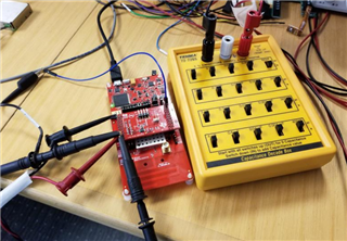
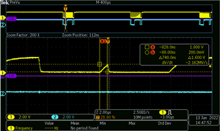
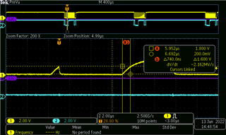
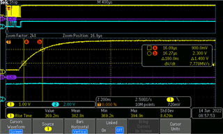
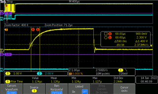
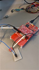
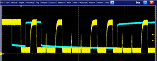
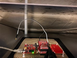
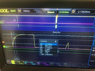
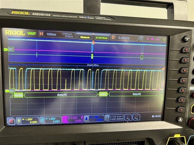
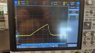
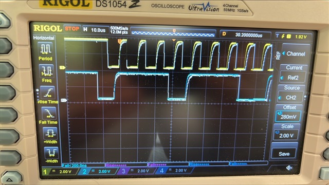
Several months ago when we were dealing with this clock runt issue, we slapped on a bandaid and kept moving, but now the problem has reared its head again in a way that we cannot bandaid.  It appears to be related to capacitance on the bus.  We can make it happen more frequently when we connect a beagle i2c protocol analyzer on the i2c.  As was before, time is lost and the mcu appears to move on to the next clock pulse in the middle of the previous pulse.  Instead of a full pulse, we just get a runt.

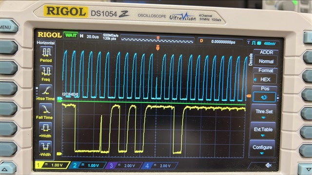
We think maybe this can be recreated by increasing bus capacitance.  In investigating, we also noticed another strange phenomenon.  When we add an additional sensor to the bus (Sensirion SPS30) or the beagle i2c protocol analyzer, the clock frequency slows down (not just changing the shape of the edge, actually pushing the pulses out so we get 99khz instead of 100khz for example).  Since the clock is driven by the mcu, it is not clear why this would happen.

Could you please investigate and provide some insight into why these phenomena are occurring?

Thanks,

Scott

  • It was pretty easily able to rig up a system using TI dev kits, and an empty example project, to replicate the problem:

    1. CC1352P1 development kit
    2. IMETER-BOOST devkit
    3. 150pF capacitor between SCL and GND (I used a decade capacitor box)
    4. Resource Explorer empty project:
      https://dev.ti.com/tirex4-desktop/explore/node?compilers=ticlang&devtools=LAUNCHXL-CC1352P1&kernels=tirtos&node=AFB7Qs6fWUCcZe3pPVyxAw__pTTHBmu__LATEST
    5. SimpleLink CC13x2 26x2 SDK
    6. Add I2C peripheral in empty.syscfg:
      Use the default SCL (DIO21) and SDA (DIO5) pins.
    7. Change empty.c source file code (attached):
      empty.c
      /*
       * Copyright (c) 2015-2019, Texas Instruments Incorporated
       * All rights reserved.
       *
       * Redistribution and use in source and binary forms, with or without
       * modification, are permitted provided that the following conditions
       * are met:
       *
       * *  Redistributions of source code must retain the above copyright
       *    notice, this list of conditions and the following disclaimer.
       *
       * *  Redistributions in binary form must reproduce the above copyright
       *    notice, this list of conditions and the following disclaimer in the
       *    documentation and/or other materials provided with the distribution.
       *
       * *  Neither the name of Texas Instruments Incorporated nor the names of
       *    its contributors may be used to endorse or promote products derived
       *    from this software without specific prior written permission.
       *
       * THIS SOFTWARE IS PROVIDED BY THE COPYRIGHT HOLDERS AND CONTRIBUTORS "AS IS"
       * AND ANY EXPRESS OR IMPLIED WARRANTIES, INCLUDING, BUT NOT LIMITED TO,
       * THE IMPLIED WARRANTIES OF MERCHANTABILITY AND FITNESS FOR A PARTICULAR
       * PURPOSE ARE DISCLAIMED. IN NO EVENT SHALL THE COPYRIGHT OWNER OR
       * CONTRIBUTORS BE LIABLE FOR ANY DIRECT, INDIRECT, INCIDENTAL, SPECIAL,
       * EXEMPLARY, OR CONSEQUENTIAL DAMAGES (INCLUDING, BUT NOT LIMITED TO,
       * PROCUREMENT OF SUBSTITUTE GOODS OR SERVICES; LOSS OF USE, DATA, OR PROFITS;
       * OR BUSINESS INTERRUPTION) HOWEVER CAUSED AND ON ANY THEORY OF LIABILITY,
       * WHETHER IN CONTRACT, STRICT LIABILITY, OR TORT (INCLUDING NEGLIGENCE OR
       * OTHERWISE) ARISING IN ANY WAY OUT OF THE USE OF THIS SOFTWARE,
       * EVEN IF ADVISED OF THE POSSIBILITY OF SUCH DAMAGE.
       */
      
      /*
       *  ======== empty.c ========
       */
      
      /* For usleep() */
      #include <unistd.h>
      #include <stdint.h>
      #include <stddef.h>
      
      /* Driver Header files */
      #include <ti/drivers/GPIO.h>
      #include <ti/drivers/I2C.h>
      
      /* Driver configuration */
      #include "ti_drivers_config.h"
      #include <ti/sysbios/knl/Task.h>


      void My_I2C_Callback_Fxn(I2C_Handle handle, I2C_Transaction *transaction, bool transferStatus)
      {
      
      }


      /*
       *  ======== mainThread ========
       */
      void *mainThread(void *arg0)
      {
          I2C_init();
      
          I2C_Params parms;
          I2C_Params_init(&parms);
          parms.bitRate = I2C_100kHz;
          parms.transferMode = I2C_MODE_BLOCKING;// I2C_MODE_CALLBACK;
          //parms.transferCallbackFxn = My_I2C_Callback_Fxn;
      
          I2C_Handle i2cHandle;
          i2cHandle = I2C_open(CONFIG_I2C_0, NULL);
          if (i2cHandle == NULL) {
              // Error opening I2C
              while (1) {}
          }
      
          uint8_t readBuffer[5] = {0};
          I2C_Transaction i2cTransaction = {0};
          i2cTransaction.slaveAddress = 0x40;
          i2cTransaction.writeBuf = NULL;
          i2cTransaction.writeCount = 0;
          i2cTransaction.readBuf = readBuffer;
          i2cTransaction.readCount = 2;
      
          while (1) {
              for(int i=0 ; i<5 ; i++)
                  readBuffer[i] = 0;
      
              bool status = I2C_transfer(i2cHandle, &i2cTransaction);
      
              Task_sleep(100);
          }
      }
      

    My decade box has a default capacitance of 50pF.
    With the default 50pF, I don't see a high rate of runts (I saw only one event during a 30 minute period when I walked away from my desk).

    However, at 150pF (shown above in the picture), I see runts every few seconds.

  • Regarding the frequency slowing down, how this can happen is explained here:

    Speed – I2C Bus (i2c-bus.org)

    The I2C standard limits Cp to the maximum value of 400 pF (Termination Versus Capacitance – I2C Bus (i2c-bus.org)) so a capacitance of 150 pF should not be a problem. Are you able to measure the capacitance to verify that it does not exceed 400 pF (I guess the 150 pF you are referring to is in addition to what is already there caused by the connected HW etc.)

    What about the rise time of SDA and SCL, have you measured it?

    Below are some similar cases where not operating according to spec. when it comes to rise time causes similar behavior as you are seeing:

    https://e2e.ti.com/support/microcontrollers/arm-based-microcontrollers-group/arm-based-microcontrollers/f/arm-based-microcontrollers-forum/711562/tm4c129xnczad-tm4c-i2c-master-generates-short-scl-clock-pulses-glitches

    https://e2e.ti.com/support/microcontrollers/arm-based-microcontrollers-group/arm-based-microcontrollers---internal/f/arm-based-microcontrollers---internal-forum/1073938/tm4c129encpdt-i2c-clock-line-missing-pulses?tisearch=e2e-sitesearch&keymatch=i2c%20clock%20missed%20pulse#

  • Thank you for the response Siri.  The third link you posted above it broken.  I am a member of the asker's party.

    Referring to the second link you posted above.  We typically use 2.32k Ohm pull-ups, but we have lowered our pull-up resistance to 1k Ohm and still observed the runt clock pulse.  I have calculated the SCL line capacitance to be about 202pF for our present setup, well within spec.

    With regards to rise times, since that was a pretty sticky point in the link you posted.  We have taken scope captures of the SCL line which show the runt along with the clock which follows immediately after the runt.  If I use the same voltage levels and the same time window on the scope for both curves I would expect the runt to have a "slower" rise time than the successful clock, if the rise time is in fact too slow.  I see the exact opposite:

    Runt:

    Clock After Runt, notice that this clock is actually slower than the runt by some small number of nanoseconds (maybe the same time, but with certainty the runt isn't increasing at a far slower rate):

    I calculated the runt rise time to be about 1.52us, which is slow but seems reasonable to me for an I2C bus running at 100kHz (I could make that a 3us rise time @ 100kHz and I'd still get valid I2C data with our fall times where they're at).  Couldn't find a rise/fall time spec in the datasheet for the CC1352P1, so it's hard for me to meet or test a spec I can't see.  Please point out this spec to me in the datasheet, I looked and couldn't find it or it's stated in a way I wasn't looking for.

    As you can tell, I'm not really buying the slow SCL rise time.  If it is then I'm curious how any of our clocks are succeeding since they all exhibit roughly the same rise and fall characteristics, including the runt itself.  Let me be clear, I'm not saying TI's internal mechanism for detecting a slow rise time isn't triggering and resetting the clock line, I'm saying the rise time IS NOT TOO SLOW, so the peripheral should not be making corrections here if it is.  Once again, it would be easier to speak to this in detail and test around it if I knew what the spec'd minimum rise time should be.

    As stated before, we've already tested with 1k Ohm pull-ups and that did not remove the runt pulse issue, so that's not the solution here as it was with Siri's linked post.  SCL line capacitance is within acceptable limits, so capacitance all by itself can't be the culprit.  Everything I've looked at points at the MCU peripheral doing things under the hood that I have no control over, and thus causing this issue.

    Thoughts?

  • Hi Siri,

    Can you please share the result of your test on a launchpad?  The last time we spoke of this issue, you could not help us because you could not recreate.  We have clearly shown how to recreate it with parts you have on hand, so please test and share the results ASAP.

    Thanks,

    Scott

  • Hi 

    I will not be in the office before Thursday, but I will see if I can run some test when I come in.

    Originally I tested on a CC1352 LPSTK but I will see if I can find a LP to test with (do not think I have the same boosterpack that you have used, but I'll see what I find.

    When it comes to the rise time, this is not stated in our data sheet, but is part of the I2C Spec.

    Max rise time for standard mode (100 kHz) is 1 us:

    Specification – I2C Bus (i2c-bus.org)

    Not being within spec. does not mean that it will fail all the time, but it is not guaranteed to work.

    Can you please try to get the rise time within spec. and see if you still see the problems then?

    Siri

  • Siri,

    Following are captures of our product's I2C bus in operation.

    30% = .9V
    70% = 2.3V

    The first one shows the rise time of SCL without any modifications (rise time = 180ns)
    The second shows the rise time with the 150pF decade box capacitance hooked up (rise time = 590ns).
    Both are well within the 1us of time that you were asking about.


  • A colleague of mine have been able to setup at test and done some measurements on our LP. He will update this thread with his results when done.

    BR

    Siri

  • Hi Siri,

    Thank you.  Can you please provide more details on the mechanism in the mcu that causes this behavior?  It is very intermittent, and things like lead lengths make a big difference when adding bus capacitance to recreate it.  We have one design exhibiting this behavior and one that does not, so we are convinced that something about our design is causing the mcu to skip its clocking state machine, or at least there is something we can do in our design to prevent it.  However, we aren't measuring any i2c specification violations so we are unsure how to prevent it by changing pull up resistances or adding buffers.  Any help from your mcu team on what might cause this and where to look or additional bulletproofing recommendations would be greatly appreciated.

    Thanks,

    Scott

  • Hi,

    This is a post to update on the efforts on our side to recreate the problem. 

    I am using a CC1352P-2 launchpad. We don't have a I-METER boosterpack in the office so I have used the BOOSTXL-SENSORS (https://www.ti.com/tool/BOOSTXL-SENSORS) add-on which features 4 I2C sensors to simulate added capacitance on the I2C bus. I also added an external 150pF cap between SCL and GND to be as close as possible to the situation you have described. 

    Finally I have used the exact same code substituted in main() of the empty project taken from the v6.10 Simplelink 13xx 26xx SDK.

    I set the oscilloscope to trigger on positive runts with a low threshold of 1V and high threshold of 2V. With this conditions I am not able to register any random runt as seen in your initial post. I have let the oscilloscope run for at least 2 hours. I tried to fiddle with the threshold to maybe catch even lower runts but nothing triggers the capture. 

    Trying to increase the capacitance ( I tried with 470pF and 880pF) on the bus leads to increased rise time as expected. Here I'm able to trigger runts on the oscilloscope with the same settings as above. However each clock edge register as a runt because it doesn't have time to reach the high state. This happens at every clock edge and not sporadically as in your case, so it is not the issue we are trying to reproduce. 

    A photo of our setup for reference:

    Regards,

    Fausto

  • One additional question: Can you see the issue as well without the I-METER boosterpack attached?

  • Hi Fausto,

    We will try to test the i2c traffic today without the boost and let you know.  Can you tell me where your capacitor is in the picture?  Is it on the breakout board?  We noticed the problem definitely gets worse with longer leads to our decade box and if they are not twisted.  Not really a real application but helping us to recreate it more often to try to understand...

    Thanks,

    Scott

  • HI Scott,

    Yes, we do not have a capacitance decade box (only a resistance one) so I soldered different discrete capacitors on a breakout board to test the behavior with the additional cap. We will consider purchasing a capacitance decade box, but to test quicker the scenario (and considering the shipment estimated time) I had to go for the above solution.

    Regards,

    Fausto

  • Hi Fausto,

    I don't think you need to buy a decade box, but maybe play with longer leads to that breakout board to see if that allows you to see it happen.

    Scott

  • Hi Fausto,

    I'm setting up to reproduce the issue without the I-METER boosterpack and noticed that the I-METER has 10K pull-ups on SCL and SDA while the SENSORS board has 2.2K on both SCL and SDA. This could be why you're not seeing the issue. Also, I noticed that the LAUNCHXL-CC1352P1 board has a 3.3K pull-up on SDA but nothing on SCL, which is odd, maybe for some other use of the pin with different booster boards?

    I'll do some more experiments and let you know if I'm able to reproduce the issue with 2.2K pull-ups.

    Thanks
    Dalton

  • Hi Fausto,

    I've confirmed that I can reproduce the issue with the BOOSTXL-SENSORS board. I have a 220pF capacitor connected between SCL and GND through wires that are approximately 8 inches long. I'm running the board in an EMI test cell and subjecting the board to 80MHz radiation. Without the radiation the SCL runts occur infrequently or not at all.

    Do you have an EMI test cell available?

    Thanks

    Dalton

  • I just caught another clock runt on one of our products, without additional bus capacitance other than the scope probe. Without the added capacitance it's very infrequent but still occurs. You can see from the measurement on the previous SCL pulse that the rise time is in spec with 2.32K pull-ups.  Can you provide any more description of how the internal circuit decides to "swallow" the clock pulse? Could it be noise sensitive?

  • We are getting really good at catching these.  Has anyone engaged the mcu designers yet?  We need to know how to get this to stop...

  • Hi, Sorry I was on leave the last two days. Tomorrow I'm coming back to the office and I'll try to access an EMI test cell in our lab, if available.

    I'll update the thread with the results. I'm still not able to replicate this issue unfortunately. 

    Regards

    Fausto

  • Hi,

    I tried to follow all your suggestions and finally managed to replicate this behavior on my desk. Thank you for the comments highlighting the situation in which it is easier to spot the runt, that was very helpful. I can see the runt every few seconds when having a jumper cable leading to 150pF capacitance which is longer than 90cm and another jumper cable of around 15cm from the cap to GND.

    Going back to your initial post: could you provide us more information about the I2C bus in your design? Do you see this behavior when adding sensor to the I2C bus through long leads or do you add them to a custom PCB? Also how do you connect the protocol analyzer to your design? 

    If you add your sensors to a custom PCB it would be helpful to be able to examine the schematics to see if we can spot anything unusual.

    Best regards,

    Fausto

  • Hi Fausto,

    Is the rise and/or fall time you observe on the runt outside of the I2C specification?  Is the total bus capacitance you measured outside of the I2C specification?

  • Hi Fausto,

    Our product uses two custom PCBs interconnected by a ribbon cable. We connect the analyzer, or scope with decoder, to test points soldered on at one of our I2C sensors. We believe the runt happens occasionally even when the analyzer is not connected. The clock runts happen infrequently on our product, but because one of the sensors we use doesn't employ a checksum on the I2C data, this occasional runt still causes problems. We attached the analyzer to get to the bottom of this problem and found the runt, which causes all off the remaining data in the packet to be corrupted. We've been able to apply a software patch but we would like to understand the cause of the problem so we can make sure it won't come back to haunt us in a different way that might get around the patch.

    I would be happy to share our schematics with you but I don't want to post them in a public forum.

    Thanks

    Dalton

  • Dalton,

    For schematic review, there is a process and you can contact your FAE, and we will take from there.

  • Hi All, 

    I have been trying to research causes of the issue both internally in TI and through online documentation in the past days. I came across this post on another forum on a competitor device that seems to be closely related. community.nxp.com/.../251800

    In this post they link a glitch (possibly due to external EM interference or cross-talk) on the SCL line to the runt, as the glitch could induce the state machine of the SPI master to prematurely start the next clock phase. 

    I have tried to look closely into a captured SCL runts and I can consistently see oscillations prior to the rising edge truncation:

    This would explain why the frequency of observation increases when having longer leads (more subject to external interference) or inside an EMI cell.

    Could you try testing the behavior changes when using shielded cables between your two PCBs. Another suggestion would be to add a buffer on the SCL line to filter out high frequency noise. 

    Regards,

    Fausto

  • Hi Fausto,

    We had considered that cross-talk could be a possibility but the problem never seems to happen near a transition in the data line so I think that rules it out.

    Were you able to find out anything about what is actually happening inside the processor when the clock pulse is aborted?

    Thanks

    Dalton

  • Hi Dalton, 

    The I2C peripheral is based on a fairly common I2C design that several manufacturer are using, hence the behavior being recorded on several devices from different manufacturers. Therefore we can't investigate what happens inside the HW unfortunately. I can only help debug at the driver level.

    I have tried using shielded cables of the same length (around 1m, which is far beyond what is advisable on this kind of designs) to connect the capacitance to the SCL line and haven't registered anymore runts.

    Also if the EMI-vulnerable part of the transaction is the rising edge of the clock, having steeper transaction (stronger pull-ups / lower bus capacitance) would decrease the probability to see this event. 

    Having long cables between two different PCBs is discouraged due to the EMI exposure that can result on the signals. Do you have plans to move your sensors onto a single-PCB design in the future? Do you have the possibility to test the behavior of I2C transactions on a single-PCB design that doesn't require long interconnecting cables?

    Regards,

    Fausto

  • Hi Fausto,

    The ribbon cable I mentioned in our design is a flex-circuit and is 1.5" long. We don't feel like this is excessive and have no plans to change our design to a single board. Furthermore, the rise time of the clock is well within spec. The bus capacitance is within spec. We believe everything is in spec and the processor is overly sensitive. This product was originally designed using the MSP432 and had no issues but that processor has gone into obsolescence. It's only been since we redesigned the product with the CC1352 that we've had issues with the I2C.

    The 1M long cables are just a way for you to easily reproduce the problem, they are not representative of our design.

    Thanks

    Dalton

  • Thank You Rogerio, I will contact our FAE.

    Dalton

  • I will close the thread for now as the discussion has moved on different channels regarding the design review. We can always reopen if any thing else relevant comes up.

    Regards,

    Fausto