This thread has been locked.

If you have a related question, please click the "Ask a related question" button in the top right corner. The newly created question will be automatically linked to this question.

Antenna's Question

Other Parts Discussed in Thread: TRF7970A, TRF7960

Hi There.

I wonder if anyone can help me understand the TRF7970A's antenna hardware.

I attached an image with certain areas highlighted in color.

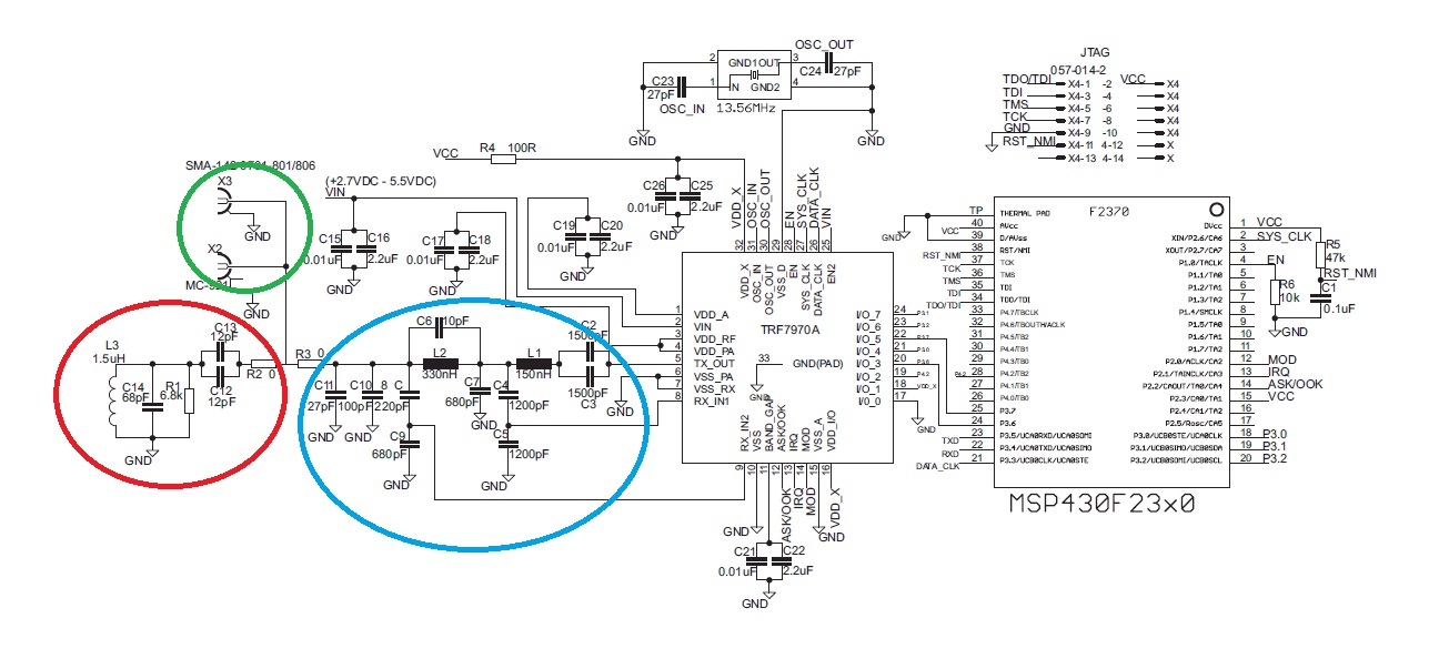
As I understand in the datasheet, the "blue area" is the Impedance Matching TX_Out circuit (50 ohms).

The "green area" is where should be placed the TRF7970A's antenna (Between 0 ohm resistors, the antenna should be connected). TRF7970A's antenna can be done step by step according to the document "Antenna Matching for the TRF7960 RFID Reader (SLOA135) ".

And here comes the part I do not understand: What role has the "red area" of the figure? Why is placed that part of the circuitry in the schematic TRF7970A? Why do not I see this part of the circuit in TRF7970EVM's hardware?

    • Blue - balun
    • Red - PCB coil antenna and impedance match circuit.
    • Green - external antenna connectors.

    Sorry but I have no answer for your last question.

    Regards,
    Maciej 

  • Hi Maciej!

    Then, If Ibuild the TRf7970's antenna as is shown in SLOA135 (3 capacitors, 1 resistor and antenna), I should do not include the "red area" in my hardware ciruit?

    Regards

    Armando!

  • For me antenna from App note seems almost the same as from datasheet. What is you want to achieve? Why not copy reference design?

    Regards,
    Maciej 

  • Well, I think there are 2 matching circuit:
    - Red area that matches the antenna coil to 50 ohm
    - Blue area that matches 50 ohm to 4 ohm

    Pay a closer attention as these are present in TRF7970AEVM hardware. 

    Why the intermediate 50 ohm? To tune independently and in a easier way the antena without complicating the circuit. Also RF instrumentation is calibrated to 50 ohm.

    If you have a blue area correctly dimensioned you can tune the antenna to 13.56MHz
    How you can do it? Just unsolder R3_0(0 ohm shunt) to unconnect the blue part. Red area now can be connected to external instrumentation through the SMA connector(green area). Playing with C12, C13, C14, R1 and an impedance calculator you can tune it.

    After this you can solder R3_0 to connect the tuned antenna coil to the rest of the circuit

    These components correspond in TRF7970AEVM to C21, C21, C24, R6

    BR,

    Vitor


  • I did it.

    I just made the PCB antenna as is shown in SLOA135.

    With C1=56pF, R1=1k, C3=47pF and C4=10pF.

    Now, 1: If I made that hardware (PCB Atenna), I should place the "red area"?

               2: I dont understand why you say that both schematics are the same. That values are not the same as I see.

  • Hi Vitor. I think that now I'm more confused.

    This is the thing. I'm building my own TRF7970A's hardware.  I placed the Blue area to matches the antenna coil to 50 ohms. Still here, I'm ok.

    I made the PCB antenna as AppNote shows: 3 capacitors (56,47 and 10 pF) and a 1kohm. Thats done.

    I included also the red area in my hardware design.  Until a while ago I did not know what the "red area" do  Now, you explain me this: "Blue area that matches 50 ohm to 4 ohm".

    Ok, then where I should to connect the PCB antenna that I built?

  • Hi Armando,

    If you have implemented the PCB with 3 capacitors (56,47 and 10 pF) and a 1kohm you have implemented the red area. That is the red area. You do not need to include another red area if you can understand me.
    The L3 inductor represents only the antenna coil that is present in your PCB
    . The terminals of the PCB antenna coil should be connected to the terminals of the L3 inductor 

    Somewhere in the app notes or datasheets it is referred that impedance of RF IO is 4 ohms for TRF7970A, TRF796... and so.
    Matching antenna can be made on two ways:

    - Design a circuit with one stage that matches directly antenna coil to RF pins (as suggested my most example circuits for NXP RFID ICs). 
    - Design a  circuit with two matching parts:
    -- circuit to match antenna to 50 ohms (red area)
    -- circuit to match 50 ohms to 4 ohm "trfx9xx RF pins (blue area).

    The last is a simpler approach that can enable the designer to match any coil antennas  with simpler calculus. With this approach if you unconnect the blue area and have the appropriate instrumentaion you can verify and measure PCB inductance very easy.

    Be carefull with your capacitor values and resistor of the red area. You must be secure on your PCB antenna inductance value to match correctly
     

    BR

    Vitor

  • All right Vitor. Then if I implemented the PCB with 3 capacitors, I should not include the red area and connect it directly to R2 (0 ohms)?


    Thank You!

  • Hi Armando,

    Yes that's it.
    If you have replicated TRF7970AEVM PCB antenna then from your last picture C1 will corespond to 56pf and C3,C4 to 47,10pF. C2 to a do not place component.

    PCB coil +C1+C2+C3+C4+R is the red part!


    BR
    Vitor 

  • Thanks Vitor, you're very kind. That's all I wanted to know, since I was making the mistake of connecting both at the same time.

    Now, I'm going to connect just my PCB Antenna. 

    Thank you so much!

    Regards, 

    Armando!

  • Hi Armando,

    just be carefull with the length of connection between the lumped components of the "red area". The coil antenna must be near as possible from the C1,C2, ...
    The length of connection will introduce a serial parasitic inductance that must be accounted, and if you don't get a very small length this can be responsible for the detunning of the circuit. 

    BR

    Vitor