This thread has been locked.

If you have a related question, please click the "Ask a related question" button in the top right corner. The newly created question will be automatically linked to this question.

Homemade PCB with CC2531 chip not recognized by computer

Other Parts Discussed in Thread: CC2531

Hi,

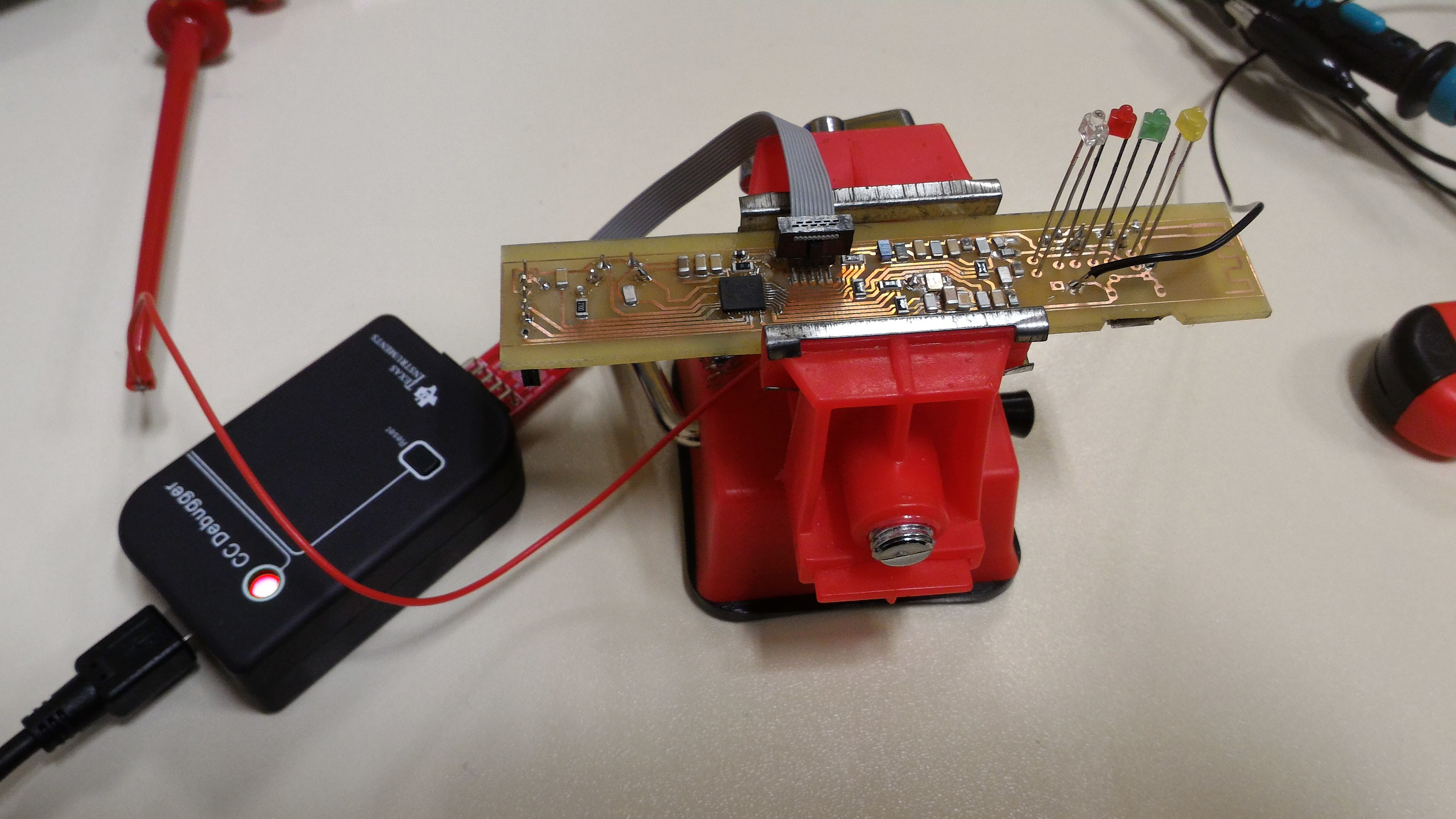
I'm a student and I have to make a customized pcb with the CC2531. I tried to follow the design of the USB dongle taking apart the parts that I didn't need.

However when I plug the CC debugger, i'm not able to communicate with the computer. The chip is not recognized by Smart RF Flash Programmer and the led of the CC debugger is still red. The firmware of the CC debugger is up to date

I used the USB dongle I have to check the voltage on my pcb and it seems to be correct. 

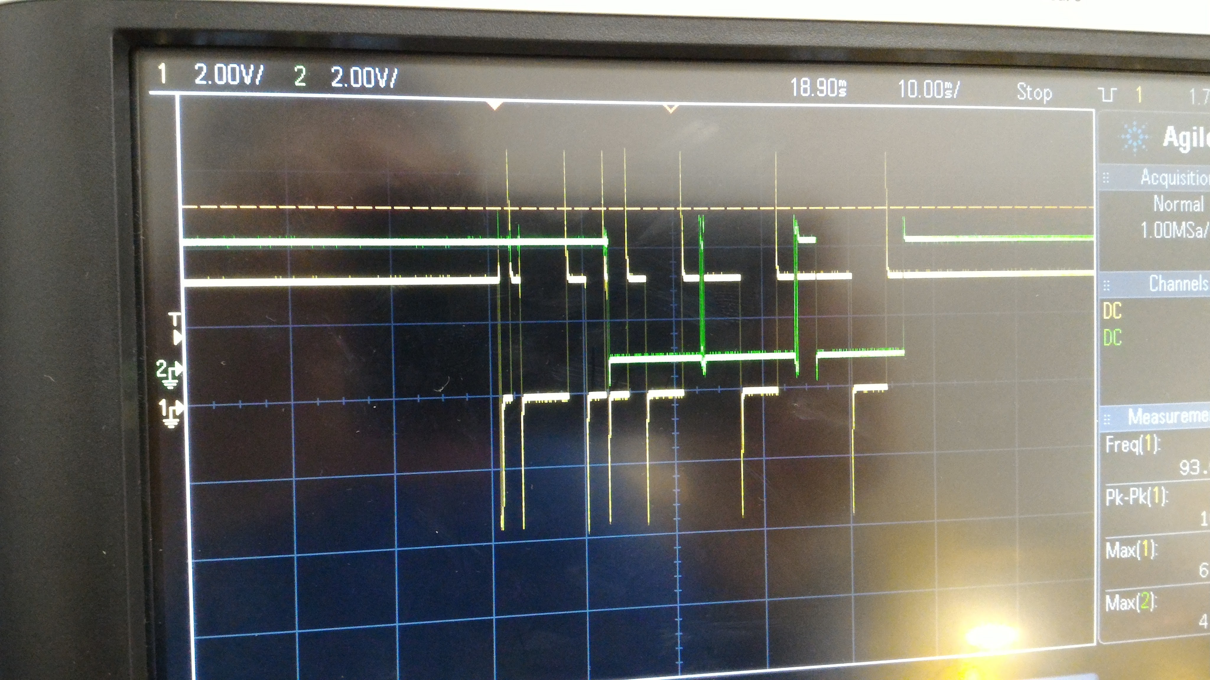
I also had a look to Reset, CLK and DATA signals of the debugger. Here are some pictures. The reset (yellow) seems correct. For data and Clock (green - the signal are identical) it seems to miss a little something in the case of my pcb.

These is the signals on my pcb

These are the signals on the dongle

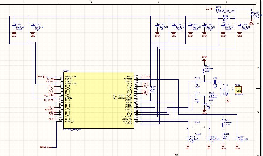
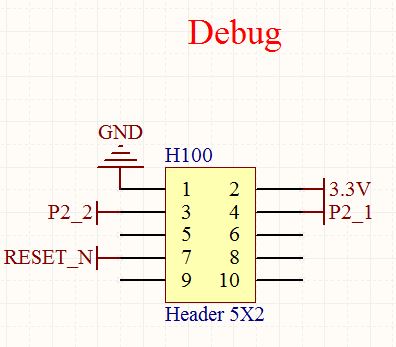
Finally here are extract of my schematics.

If you have any idea of what the problem could be please share.

And of course, if you need more information, i would be please to answer your questions

Kind regards,

  • What power do you use? How many boards have you tested? Do you have a picture of your set-up?
  • Thank you for your reply,

    For the test we use an external power source of 3.3V directly connected to the 3.3 we see in the schematic above with the CC2531.

    Unfortunatly we run out of time to conclude our project to make a second board today. So for the moment we try to make this board work.

    What do you mean by set up ? Here is a picture of our board

    Kind regards

  • Do you have ground vias under the chip? this design is not good and very different from our designs. If you get to program the device, the RF performance will be very poor. I suggest that you start over and this time follow the reference design. The RF components in the balun and filter and decoupling capacitors must be placed close to the chip pins like in our ref design.
  • Sorry, but the layout on this board is not good. Any reason why you didn't follow the reference design?
  • Hi,

    Sorry for the late answer. We didn't follow exactly the reference design because we wanted to make our own product which includes the CC2531.

    Moreover we had to move away the capacitor because we didn't have the good tools in our lab to use 0402 capacitor. 

    So maybe we were to optimistic with the homemade way. 

    We found another plan. Thank your for your help

    Kind regards