This thread has been locked.

If you have a related question, please click the "Ask a related question" button in the top right corner. The newly created question will be automatically linked to this question.

TRF7970A: TRF7970A: Troubles on using TRF7970A with some voltage values on Supply Input

Part Number: TRF7970A

Hi support / community,

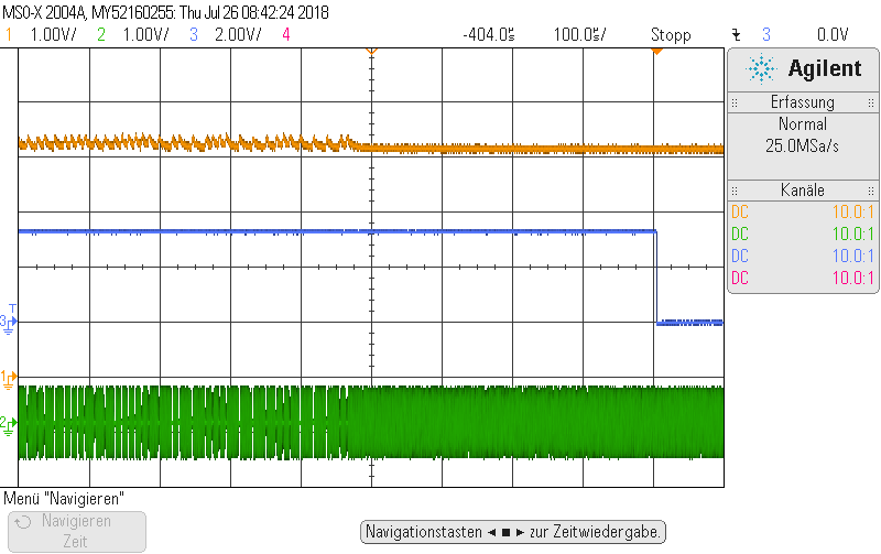
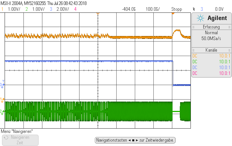
we need your help. We have TRF7970A in a battery-powered application. We use an external LDO for limiting supply voltage for TRF to 5V, but if battery voltage goes down, the supply for TRF goes also down until 4,3V. Everything works fine on the top and on the bottom of this voltage range, but we have troubles within a small area in the middle, where the Vin for TRF is about 4,6V. Our settings are 5V operation and automatic regulator settings. The problem is: we can not read even UID from a ISO14443A transponder.

Here are the captures of Vin for the hole range of battery voltage. In the middle we have a "dead zone".

To exclude problems with the power supply circle, we replaced it by a good power supply unit but the error still remained.

If we switch from 5V to 3V operation, the the error disapeares. Unfortunately we can not let by 3V because we need more power for reading DESfire incl. encryption.

All other changes on the settings for TRF we have tried, didn't show any improvements.

Our hardware design for TRF is based on the design guide from TI and has no special deviations from it.

Please give us some hints how to solve this problem.

Thanks, Alex

  • Hello Aleksandr,

    First, can you measure the VDD_RF voltage output when using the automatic gain control setting?

    Second, since your minimum voltage may be as low as 4.3V, can you additionally set the Regulator Control register to 0x00 which is for VDD_RF = 4.3V and test the performance across voltage levels?
  • Hello Ralph,

    please see following pictures from VDD_RF for both cases: on good and on bad performance.

    Orange line is VDD_RF, Green line is radio signal (measured on an antenna), blue is just a trigger signal. 

    1. reading good, whole sequence

    2. reading good, zoomed in

    3. reading bad, whole sequence

    4. reading bad, zoomed in

    We tried out all voltage levels, also VDD_RF = 4.3V. The error disappeares completely only if we set 3V operation.

    In addition is to say, that this problem exists only on a subset of our devices, not on all. But until now we couldn't find any difference between them.

    Best Regards, Alex

  • Hello Alex,

    Thanks for all this data, I haven't been able to analyze it as much as I'd like today so I will probably only be able to offer feedback tomorrow.

    One clarifying question: "We tried out all voltage levels, also VDD_RF = 4.3V. The error disappeares completely only if we set 3V operation."

    Is that meaning the VIN supplies to the device or the Regulator Control settings?
  • Hi Ralph,

    I meant Regulator Control Setting (Register 0x0B set to 0x00) to set up VDD_RF = 4.3V as you suggested.

    We also tried Half Output Power (Register 0x00, Bit 4) and RX_IN2 (Register 0x00 Bit 3) and different settings for Gain Reduction (Register 0x0A, Bits 2+3).

    Nothings helps to get the communication stable on 5V operation.

    Best Regards, Alex

  • Hello Alex,

    Reviewing your waveforms, it looks like there is a spike on VDD_RF when your trigger signal falls, and that spike causes a break in the RF field output more notable than just modulation. That could possibly explain the read failure.

    Are you issuing the same command in both cases?

    Can you describe what you are tracking with the trigger signal?

    On another train of thought I had would be if have you done any monitoring about the current draw for your system? Given it works with 3V settings, I had been thinking that it could be that the 3V settings are drawing less current in and that is why it is successful, but then half-power would work too... after all, it should have a max draw of 78mA vs 100mA for 3V. That said I'd still like to understand if your current supply is providing enough energy, and also if the failed behavior on half-power mode identical? In other words, do you see any notable gaps in the RF field due to the VDD_RF spikes in that situation as well?
  • Hi Ralph,

    to your questions about colleration between spikes, trigger signals and command sequence:

    - test trigger signal rises directly before we start reading the transponder => send first command "REQA"

    - test trigger signal falls directly after we've done reading UID (whatever the result is). If the reading attempt was unsuccessful, we turn off the radio field and start after a short delay next attempt.

    So, the one bigger spike at the end of last diagram (see above) is not the reason of the problem, but the result: we turn off the field and VDD_RF goes high. The error happens earlier.

    Yes, there is the same command sequence in both cases: REQA and anticollision loop.

    Please let me explain our problem again.

    Because of battery supply, Vin voltage in our system drops with time from 5,0V down to <4,3V.

    TRF7970A works good on the top and on the bottom of this range of Vin, but not in a small area in the middle. See this osc. pictures of Vin over the whole range of battery voltage (Text = Vbatt):

    To exclude problems with the power supply circle (LDO that produces Vin), we replaced it for tests by a good power supply unit but the error still remained.

    With good power supply unit I mean this one: http://www.sm5cbw.se/hameg/hmpwr/hmp4040-data.pdf.

    So may be, there is something wrong with the internal regulator that provides VDD_RF?

    In our hardware design we redeemed design hints form TI and buffer VDD_RF with 10nF + 2,2µF, close to TRF7970A.

    I hope, you can give me some hints for reasons of this unlikely behaviour.

    Best Regards, Alex

  • Hello Alex,

    Bringing up the topic of filter caps, that prompts me to wonder about some other hardware questions. Do you have the same 10nF+2.2uF caps on VDD_X? How is VDD_X used in your system? Do you have pulldown resistors on ASK/OOK and MOD? How are EN and EN2 connected and do either of them have any pulldowns?

    To be honest, a schematic review might be a good step here, as I haven't seen behavior like you are describing before. If you don't want to post the schematic on E2E you can friend me and send it via private message that. (Friending can be done by clicking my name to go to my profile and then clicking Connect near the top right).

  • Hello Ralph,

    thank you for the support so far!

    to the questions:

    - VDD_X is not used in our system.

    - VDD_X is puffered by 10nF + 100nF + 1µF.

    - ASK/OOK, MOD, EN, EN2 and all other digital signal lines are driven by main µcontroller and will be set directly to high or low condition upon need. Is an additional usage of special pull-ups or pull-down required?

    You're right, the review of the schematics may be helpful how. So, if you can confirm that there is nothing more to improve by changes on the settings for TRF, I would like to hand over this request case to our hardware designer. I am just the firmware developer, you know. He will be available first at the end of this week. I will advise him to tack on this request case and contact you here or via private message.

    Best Regards, Alex

  • Hello Alex,

    Thank you for those details.

    Even though VDD_X doesn't have to be used externally, it is an important regulator internally that when not handled properly can result in poor device behavior. From our experiences, using just the 2.2uF and 10nF capacitors as filter caps for the regulator is what provides the best performance and alternate values have caused issues before. Could you please have the hardware engineers change the capacitors to those two recommended capacitor values and then re-test the circumstance in your system?

    Also small note but I edited my prior post to correctly state '10nf' instead of what I had incorrectly written which was '10uf'.