This thread has been locked.

If you have a related question, please click the "Ask a related question" button in the top right corner. The newly created question will be automatically linked to this question.

CC2510: Problems flashing cc2510 using Smart RF Programmer

Part Number: CC2510
Other Parts Discussed in Thread: CC-DEBUGGER

Dear all,

I was trying to flash a batch of cc2510 for one of our products and ran into problems.

we are using a cc2510 which is controlled by a pic32 in our device which basically has a special programming mode (our collaborator programmed) which should allow the cc2510 to be programmed using the debug interface.

We are using Smart RF Programmer to load a hex file on the chip and whatever configuration I use (fast or slow) I cannot transfer the program on the chip. If I use fast smart RF tells me that the erase step failed and if I use slow the readout of hex fails. If I read back what is on the chip into a file I basically get a bunch of 0 and 1. However the chip is detected and the smart RF programmer also identifies ist correctly as an cc2510.

The procedure itself works as I tried it with an older batch of the same device and writing the program on these chips was no problem.

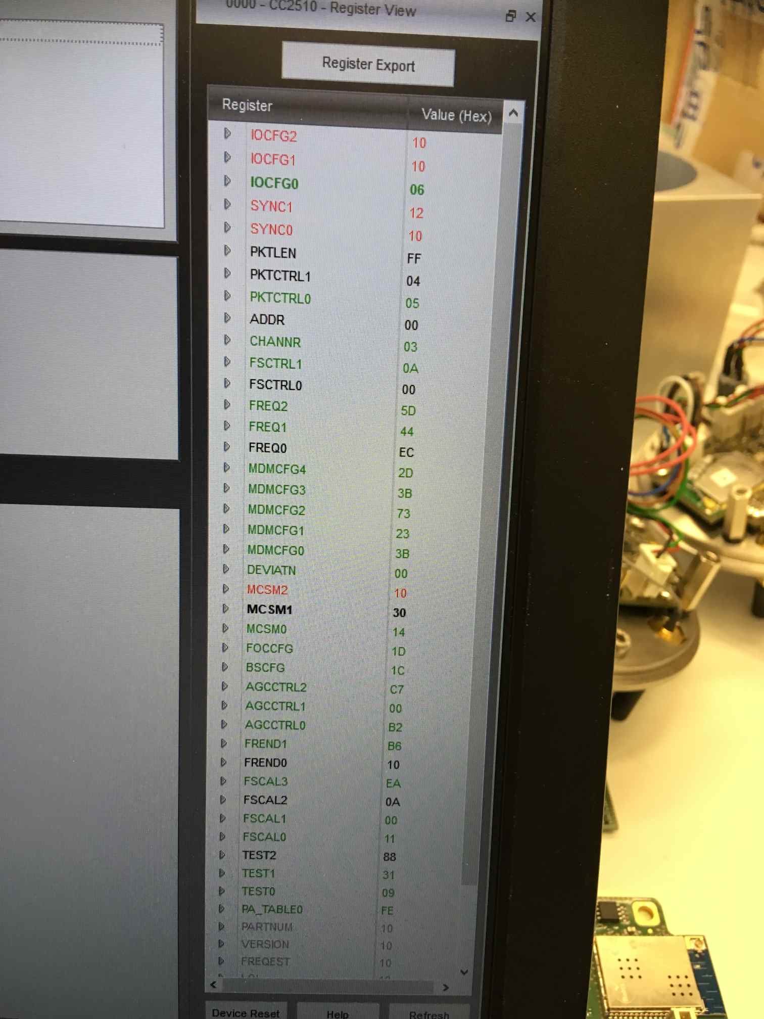
Then I tried SmartRF Studio to communicate with the chip in an effort to find out more and when connecting to the chip I get the error message, that the chip is in an invalid state on startup.

The register view shows this:

Can somebody help me understand what the problem is with this batch of chips and if there is something I can do to actually program them? Any help would be greatly appreciated.

BR Klemens

  • Hello Klemens,

    Could it be that you have locked any of the flash pages on your CC2510? Refer to chapter 11.3 in the datasheet. 

    -Simon

  • Hello Simon,

    Thank you for your response.
    I don't think so, at least I have selected non of the write protection options in the smart RF programmer.
    I have refered to section 13.16.3 in my data sheet of cc2510 (may´be we have a different one) and I don't think I have written any of these bits, at least no on purpose.
    Also the chips should arrive with no program from our manufacturer and even if I use a brand new one I can't write anything on there in the first place.
    How can I find out if the flash pages are locked?

    BR Klemens
  • Hi Klemens,

    How are the PIC32 and CC2510 interconnected? Is it any chance that the PIC32 is interfering with the CC2510 debug interface? Can you post your schematics here?

    -Simon
  • Hi Simon,

    I'm afraid the shematics are propriatary, but I try and answer your question.

    The PIC32 is connected to CC2510 with P1_4 to P1_7 and it controls the RESET_N input for the CC2510. DC, DD, MISO, MOSI, Csn and SCLK are directly routed to a programming plug with no outside interference.

    In Programming mode the PIC32 gives up control of the reset channel so it can be controlled by the cc-Debugger. This is indicated by the led on the cc-debugger being red when the PIC32 is not in programming mode and it turning green on reset when it is and it is recognized as a CC2510 by the SmartRF programmer software after this has happend.

    So I think that this part works, also the procedure itself has worked with the last batch.

    The only thing I'm not sure about are the IOCFG2 and IOCFG1 registers which have something to do with the P1_6 and P1_7 according to the datasheet of the cc2510, but I don't understand exactly how these topics are connected and the PIC32 is talking to the CC2510 via these two pins.

    Hope this helps, Klemens

  • Hi Klemens,

    P1_5, P1_6 and P1_7 can be used as radio debug pins or to control an external PA and/or LNA, see Table 73 for what you can use those pins for. Make sure that you don't have configured P1_7 for radio debug if you need this pin for other purposes.

    Since this worked on your last batch I assume the SW is working as it should, then I'll recommend you to check the soldering of the chip and maybe do a reflow to verify that the gnd-pad is connected properly.

    -Simon
  • Hi Simon,

    Sorry for the late reply, I was at the manufacturers site and we tried swapping the chips from the old device that works to one of the new boards and vice versa. Apparently there is something wrong with the board, because the new chip on old board worked and the old chip on the new board showed the same problems.

    We are still trying to figure out what is wrong with the boards, I will give an answer to that once I know. But to get at least some boards up and running, is there a socket for the cc2510 form factor so I can build a programming rig to program some chips before I put them on the boards?

    Best regards,

    Klemens

  • Hi Klemens,

    Unfortunately we don't have a socket board for sale. If you send me a friend request here on E2E, you'll be able to send be your design files privately and I can assist reviewing the design if needed.

    -Simon
  • Hi Simon,

    We checked with the manufacturer and you were right, the ground wasn't soldered on properly. After resoldering the chips everything works as expected for now. Thank you for your time and help, it did help me out a lot.

    BR Klemens