This thread has been locked.

If you have a related question, please click the "Ask a related question" button in the top right corner. The newly created question will be automatically linked to this question.

CC8520: Interference between multiple networks

Part Number: CC8520

Hi, there are some old threads in the Purepath Wireless Forum about interference between multiple devices.  There's also a diagram in the User Manual Section 2.4.6 describing a situation where one device may be transmitting and jam a nearby device that's trying to receive.

There was an old post here where they referred to a video demonstrating 4 networks working at the same time in the same room, and without being synchronized.

https://e2e.ti.com/support/legacy_forums/purepath_wireless/f/382/t/58314

The link to the video no longer works, I was hoping someone could track it down for me so I could compare TI's results to my own.  I'm seeing audio dropouts on 3 unsynchronized networks when the slaves are within around 2 feet of each other.

e2e.ti.com/.../235858.aspx

Thanks,

Arthur

  • Hi Arthur,

    The video you are looking for is probably this one:
    www.youtube.com/watch

    Best Regards,
    R.M
  • Thank you that's definitely the one.

    Per my understanding, Timeslot Aligned Masters are not used in this video. Can you explain why they are not needed in this demo, and how the situation could be improved by aligning the masters' timeslots? Would the tx & rx be able to be moved farther away from each other than the few feet demonstrated here?

    In my application I think it's more likely that a protocol Slave would jam another Slave, than for a protocol Master to jam another Master. The Masters tend to be placed farther apart from each other, while the Slaves are wireless microphones so they can be brought very close to one another. If I implement Timeslot Aligned Masters, does that effectively align the transmissions of the protocol slaves as well so they don't interfere with each other? I know that the PAEN and LNAEN signals are not always the same length so I wasn't sure if that could cause the Protocol Slaves to be misaligned even though the Protocol Masters are aligned.

    Thanks,
    Arthur
  • Hi Arthur,

    In a setup like you explain with slaves as wireless microphones timeslot aligned masters should also effectively align the transmissions from the slaves. This is because the packet size transmitted from the masters should be constant and equal on each master in your setup (probably only a ACK) effective aligning the data from the slaves too.

    When it comes to the video I'm afraid I don't know the answer to your question on why timeslot aligned masters where not needed in that setup and how far away tx & rx could have been moved.

    Best Regards,
    R.M
  • Hi R.M.,

    Can you attempt to explain how a specification like Adjacent Channel / Alternate Channel Selectivity from the datasheet would relate to the jamming problem shown in Figure 37 of the User Manual?  The datasheet Selectivity spec only extends as far as +/-8MHz (43dB) but I'm interested in what the selectivity would be when two un-synchronized Purepath Devices are operating at frequencies at opposite ends of the 2.4GHz spectrum.  

    I know for example that at a separation of 3ft, my devices report an RSSI of -15dBm.  So with timing misaligned for worst-case jamming, and using -15dBm on Channel 1 as the interfering signal level, I should expect to still receive the wanted signal on Channel 3 if it's at RSSI of (-15-43) = -58dBm or better.  If the wanted signal is on Channel 4-18, I should be able to receive it at even weaker RSSIs but I don't know what these levels would be as they're not specified in the datasheet. 

    These numbers may not be exact but can you correct me if I'm severely misunderstanding?

    Thanks,
    Arthur

  • Hello, this issue is marked as "TI thinks resolved" but I am still waiting an answer on my post from June 5.

    Thank you,

    Arthur

  • Hi Arthur,

    I think your analysis is correct based on the appnote 

    From your example, I am making the assumption that you are interested in the 2Mbps mode. The appnote shows the 2Mbps and 5Mbps selectivity numbers, while the datasheet only shows the 5mbps selectivity numbers. I also notice that the datasheet and appnote are different by 1dB. (the datasheet would supercede the appnote). And you are correct the datasheet and appnote only show +/-4MHz and +/-8MHz selectivity numbers.

    In your case

    [] Interferer: Channel1 (8MHz away from signal), -15dBm

    [] Signal: Channel3, -58dBm

    This meets the criteria of selectivity, of the RF device tolerating a 43dB larger interferer 8MHz away, and be able to receive the signal. (per appnote)

    Are you experiencing that you cannot receive the signal, as e.g. -15dBm interferers are in play?

    Regards,

    --Gunter

  • Gunter,

    I had not seen this app note before but it's very helpful thank you!

    In my application it seems I will always get audio dropouts even at short range if I watch on the oscilloscope and wait until the phases of the two networks' PA_EN signals are misaligned (masters 3ft apart, slaves 3ft apart, and slaves 20 ft from masters).  If there is no interference the line of sight range of the system is around 1000ft with little to no dropout so the effect of the interfering devices is very significant.  It doesn't seem that the two networks are able to avoid each other for example by one network going to the high bands and the other going to the low bands.  2mbps is my over the air data rate.  

    I am trying to conclude if the severity of the interference effect is about the level that would be expected, or if there's some deficiency specific to my implementation.

    Thanks,

    Arthur

  • Gunter,

    For Table 4 in the app note I would expect to see it documented how far apart the Master and Slave were and what bitrate and TX power were used.  It would make sense that PPW can tolerate more interference as the link budget goes up and that has been my finding from practical testing.  Do you think you could find this information?

    Thanks,

    Arthur 

  • I need to ask how the Timing Synchronization works and whether I can spoof that signal from my CPU in order to align PPW systems that can’t be physically connected by a wire.  I need to know how sensitive the synchronization signal is to being adjusted, why it has a period of 2x the time slot duration instead of 1x, and at what point audio gets interrupted if the synchronization signal disappears from a Timing Slave.

    I would like to randomly delay the Timing Slave's incoming alignment signal whenever we have audio slices lost, and leave it alone when audio is working well.  In this way maybe we could stumble upon the correct alignment for two nearby PPW networks.

  • Hi R.M.

    do you have an update first on Arthur's question about the channel selectivity and tolerance of interferers in a typical system. The reason we need that answer is that we need to know what expected system performance Arthur should see.

    Then we can address the synchronization questions secondly.

    Regards,

    --Gunter

  • Hi Arthur,

    Regarding the channel selectivity, it is hard to give a good quantitative number here in addition to what is already in the datasheet. Generally you can expect some issues when several PPW networks run in close proximity with each other as the channels are quite wide. When it comes to the network detecting interference with each other and separating into high and low channels in order to avoid each other, this would only work if it is the masters experiencing the interference. The reason for this is that it is only the masters that perform the LBT routine before transmitting while the slave does not. If the slave is interfering with another slave, the master would not know this.

    As for the Timing Synchronization feature, this could be spoofed by the CPU if you want as it is normal H/L signal. In this case, I would recommend you look into how the signal works in a Master -> Master use case as described in the User's Guide and use that as a base line for your spoofing attempt.

    As for "I need to know how sensitive the synchronization signal is to being adjusted, why it has a period of 2x the time slot duration instead of 1x, and at what point audio gets interrupted if the synchronization signal disappears from a Timing Slave." - Could you elaborate a bit on this for me as I'm not sure I fully understand what you are referring to here.

  • I thought LBT wasn't the only factor in determining if a channel was good.  I thought packet error rate might also be used in which case if a Slave is being interfered with that channel should be marked as not good.  Are you saying that's not the case?

    Your question in the final paragraph - I need to manipulate the spoofed timing signal.  I have observed my Timing Master signal has a period of 5.5msec (2x my timeslot of 2.75msec).  If a network is operating well I want to give its Timing Slave an synchronization signal with a period of 5.5msec.  If it's not operating well, I want to give it a synchronization signal with a period of 5.49msec.  Will the system tolerate that?

  • Hi Arthur,

    The coex mechanisms consist of the adaptive FH scheme and the master LBT. As far as I'm aware, packet error rate is not directly part of the mechanism other than the FH scheme trying to work towards using active channels that give good QoS.

    As for the timing signal, the synchronization would be on the signal toggle which means every 2.75 ms if your period is 5.5ms with a 50/50 duty. As for the offset, I think the sync. signal period (or toggle period) need to be at least the length of the time slot. Have you had a closer look at chapter 2.4.6 in the User's Guide? 

  • M-W,

    Back to the original question, are you saying two PPW networks won't avoid each other in frequency if their Slaves are physically close and interfering with one another but their masters are not physically close?  Then if the Masters are close to one another the PPW networks WILL avoid each other in frequency?  From previous discussion of Selectivity on this post, we know that the networks must be separated by more than two channels in order to not interfere.

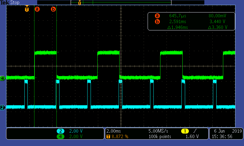
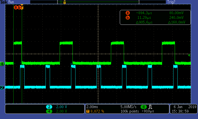
    I don't see the sync timing given in the user guide.  I measured the sync timing with one of my networks configured as a Timing Master.  The duty cycle is not 50%.  The duty cycle varies based on whether a Slave (microphone) is connected to the network or not.  I will attach these.  The green trace is the timing sync signal generated by the Timing Master and the blue trace is the Timing Master's own PA_EN signal.

    What will happen to the network if I increase or decrease the period of the sync signal slightly as I asked in my post from June 14?

  • Hi Arthur,

    First of all, it seems that I was wrong on the synchronization signal, it seems the falling flank of the signal is what marks the start of the timeslot (the signal goes high when the master start preparing for the next timeslot). It is also only generated for every other timeslot.

    What would happen if you increase/decrease the signal would need to be tested but the recommendation is to make all masters/slaves fully synchronized in time (master/slaves perform TX at the same time).

    As for avoidance, this is true as the master do now know the reason for the slave not responding (it might simply be turned of). There is the possibility to adjust the channel map dynamically which means you on the host processor side could make a decision to move around the channels in order to avoid another device. As only the master performs the avoidance routines, it could be beneficial to switch the roles of the master/slaves in the system as master -> slave communication is more reliable. It could also help to use the 5 Mbps mode if possible as this would allow the system almost double the amount of retries.