This thread has been locked.

If you have a related question, please click the "Ask a related question" button in the top right corner. The newly created question will be automatically linked to this question.

RF430FRL152H: GUI Interface command

Part Number: RF430FRL152H

Dear all,

Hello my name is minhyung kang.

I am using RF430FRL152H and MPS-EXP430G2ET + DLP7970ABP to create a customboard.

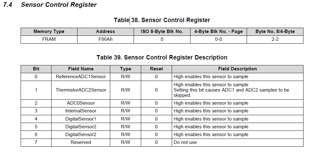
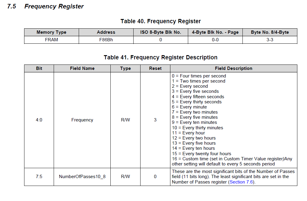
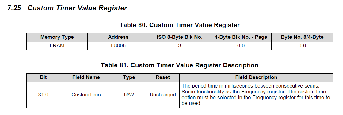
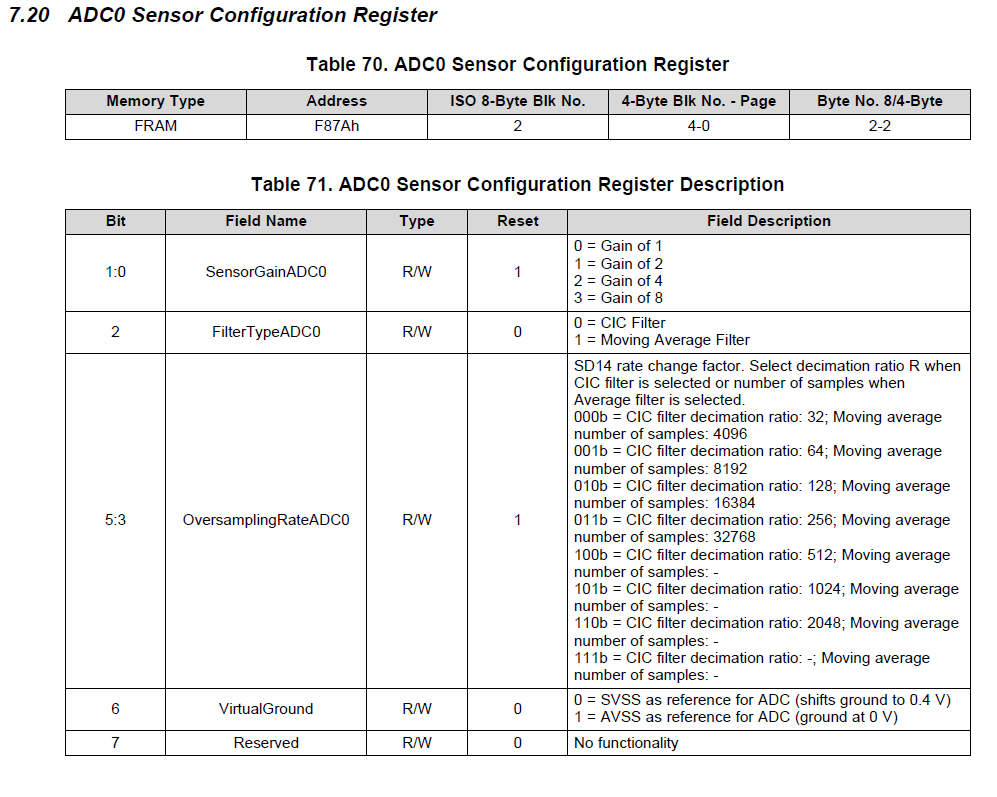
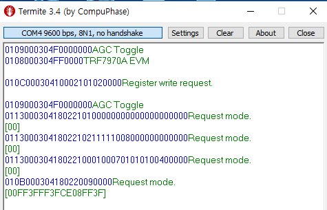
I want to know the command like the command in the below figure that set the custom time register, oversampling rate and sensor control register that can be set in GUI Interface.

Can you help me??

  • Hello Minhyung,

    the commands in your screenshot are the right commands to set the requested registers.

    The command is constructed as follows:

    This command writes 8 bytes to block number 2 which contains the registers as described in the Firmware Users Guide:

    Command: 01130003041802210211111008000000000000 Response: Request mode [00]

    Each byte of the command explained:

    01 - Startbyte

    13 - Length of command

    000304 - fix value

    18 - transmit command

    022102 - ISO 15693 write block command -> last byte (02) is the block number

    1111100800000000 - data for block 2 which contains the registers as described in the Firmware Users Guide starting from section 7.18 (Block Nr. 2; bytes 0,1,2,3)

    0000 - fix value

    Best regards,

    Helfried

  • Dear Helfried

    Hi. Thank you for your kind reply. I understood your hint. But I did not fully understand it.

    The meaning of what you said to me means to modify the part that sets the custom time register, oversampling rate and sensor control register in Command (1111100800000000), right?

    But I do not know which part of the command is part of setting custom time register, oversampling rate and sensor control register ...

    I want to enable only the ADC0 sensor in the sensor controlo register, set the frequency register to custom time, set the custom timer valuse register to 40 ms, and set the oversampling rate to 32.

    But I do not know where to modify it ... and I do not know exactly how to fix it. I want to know exactly which part of the command should be modified. And can you show me some examples of modifying the Command?

    The image below is about the registers I want to set up.

    Best regards,

    minhyung

  • Hello Minhyung,

    in the register description the first line in the table shows "ISO 8-byte Blk No." this is the block number you have to write to.

    under "Byte No. 4/8-Byte" you can see the byte number where the register is located in that block.

    Section 7.1. of the Firmware Users Guide shows that in detail.

    This means you can not write only one register you have to write 8 registers as a block.

    Look up the block number of the register you want to modify and replace it with the block number in the command (9th byte in the command - last byte of the ISO 15693 write block command I explained) then follows the data for all 8 registers located in that block.

    My example command shows a writing of 8 bytes (1111100800000000)  to block number 2.

    This data is related to the following registers:

    0x11 - Reference-ADC1 Configuration Register
    0x11 - Thermistor-ADC2 Sensor Configuration Register
    0x10 - ADC0 Sensor Configuration Register                        -> change this value in your case to 0x00  for oversampling = 32
    0x08 - ADC2 Sensor Configuration Register Description
    0x00 - Initial Delay Period Setup Register
    0x00 - JTAG Enable Password Register
    0x00 - Initial Delay Period Register
    0x00 - not used


    Best regards,

    Helfried