This thread has been locked.

If you have a related question, please click the "Ask a related question" button in the top right corner. The newly created question will be automatically linked to this question.

TRF7970A: FIFO is filled with extra zero bytes and reading fails

Part Number: TRF7970A
Other Parts Discussed in Thread: TRF7960A

Hi!

We have single board with design similar to reference design, matching circuit is with custom values. Application is for RFID ISO14443a. On some occasions individual boards are having poor sensitivity like issues. TRF7970A FIFO is padded with 0x00 zeros when tag is located at normal reading distance which is about inch from the PCB. Extra bytes are always 0x00. Some of the tag bytes may be found from the start of the FIFO buffer and reading fails due to wrong ID. It's random if it's read correctly or is it padded with variable number of extra bytes. At very close distance usually working just fine. TX power is set high in Chip Status Control register.

Issue is found from about 1% of the boards and started on spring 2019. No problems faced before this.

I think the problem is self-jamming where TX signal is leaking to RX side at too high level, but have no proof. This might be due to component value variation if something is at the very edge.

Any suggestions from where to start?

  • Hi,

    I haven't heard about a problem like this before. Have you tried to swap the TRF7970A device from a working board to one with that issue to identify if the issue moves with the board or the device.

    I will contact a colleague about your request and will come back to you the next business days.

    Best regards,

    Helfried 

  • Replaced TRF7970A to 3 boards from presumably working ones. Boards were tested but there is always possibility that the issue may occur in long term usage. Better say that at least in symptomatic boards the issue occurs more often.

    Case I: Problem transferred to previously working board.

    Case II: Problem transferred to previously working board, occurs rarely.

    Case III: Both of the boards are now showing symptoms.

    It seems now the problem is following the TRF7970A device, but this small number of samples is not giving enough certainty.

    Example of the FIFO layout when problem occurs:

    Bytes in fifo 127
    Read '08200000000000000000000000000000000000000000000000000000000000000000000000:' from FIFO

  • Hello G0willy,

    Sorry for the delay, Helfried had to unexpectedly be out and I didn't notice this thread until you replied today. That's our bad.

    Can you have a look with an oscilloscope at the RF field output when this error is occurring? Is it a strong continuous field, or are you seeing any interrupts with the RF field?

    What is the input voltage to the device, and what is the setting for Register 0x0B (Regulator Control)?

    Also regarding the FIFO, what is the FIFO length read from the device when you observe this issues?

  • Thank you, no worries about the delay. Made some measurements with a good and failing devices.


    1. Here is a successful read from a tag located near field:

    This is what it should look like, right? Backscatterer fields are visible.


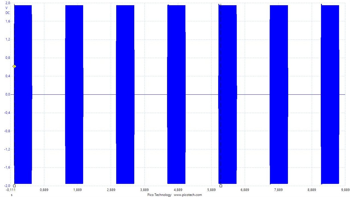
    2. Next RF-field with no tag from a good working device:

    Periodical field and no interference seen at least with this accuracy.


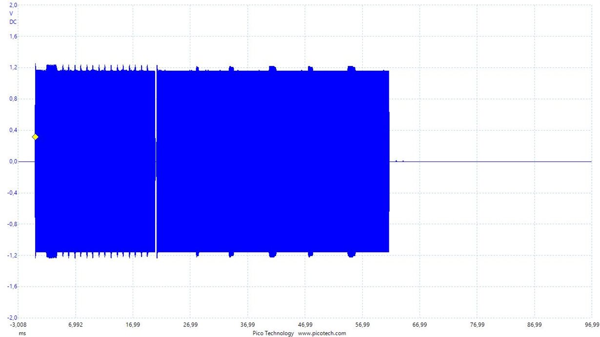
    3. Next is RF-field with no tag from a frequently failing device:

    Strange non-periodic field with some interference-like signal.


    4. And the last one is from a failing read with tag and the FIFO is padded with with 0x00 bytes:

    Still unclear in what phase the device is failing. It is probably one of the last 3 fields. Is the device RF disabled on FIFO error bit=1 until removed? It should be possible to catch accurate period from the field when error occurs if I just know what it is.

    Input voltage is 5V and register 0x0B = 0x07.

    FIFO length is usually 127 (full) when issue observed, but it can be shorter. When the issues is observer FIFO usually reads a few "real" bytes and the rest is zero.

    We have now firmware set to half-power output and got good first test results with a failing device. More study to be done.

  • Hello g0willy,

    I am going to ask Helfried to take over helping with some of this issue - the waveforms confirm what I suspected, and the half-power mode working also does. You can try setting the regulator control to a lower setting and probably will see better behavior too. Anyways, he will be able to better guide you through the steps to resolve that issue in your system.

    Also as a general note, the FIFO length should never be allowed to fill up - the FIFO watermark levels need to be adjust if the MCU isn't having enough time to read the FIFO before it fills. Ideally you should read the FIFO the moment the first 0x60 occurs for the amount of bytes of FIFO length reported. Then continue to do so until the 0x40 comes which would be your final bytes. I'd recommend addressing that in your firmware.

  • Thank you for your support. I look forward to your comments and suggestions.

  • Hi,

    I have send you a friends request via email.

    Best regards,

    Helfried

  • Vdd_RF set to 4.3V (register 0x0B = 0x00), as recommended in the datasheet, is behaving much better than the 5V we are using. Of course needs a lot of testing to be sure we are not generating a new issue. Interesting study what would be optimal Vdd level not significantly reducing the range.

  • What is the default register value for 0x0B Regulator and I/O Control Register ?

    On datasheet:

    table 6-21: default to be 0x87 (Regulator = Auto & 250mV delta).

    6.3.1: default delta level is changed from 250mV to 400mV, as also noted on 2. Revision history.

    table 6-41: delta is 400mV for automatic regulator setting.

    -

    On chip startup the default value we have is 0x87 (250mV delta).

    -

    Example firmware sets REGULATOR_CONTROL to 0x01 (manual regulator set, 4,4V  @5V supply).

    -

    TRF7960a datasheet recommends using 250mV delta for best PSRR.

    -

    Information given is confusing, what do you suggest using with TRF7970a?

  • Hello g0willy,

    I see that we missed an update on the TRF7970A datasheet, the automatic regulator control is 400mV for the TRF7970A. Do not look at the TRF7960A specs for this, that device handles automatic regulator control differently and you cannot apply what is said in that datasheet to the TRF7970A.

    The default setting is 0x87 which is automatic regulator control.

    Have you replied to Helfried's request to get further support on this?

  • Thank you for the information.

    I have contacted Helfried via email.