This thread has been locked.

If you have a related question, please click the "Ask a related question" button in the top right corner. The newly created question will be automatically linked to this question.

TRF7970A: TRF7970A

Part Number: TRF7970A


Hi,

I am opening a related question cause this is the same project, I still have issues with the RFID.

Issue description:

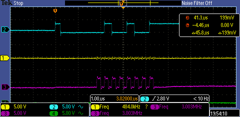
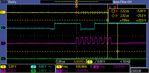
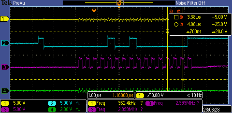
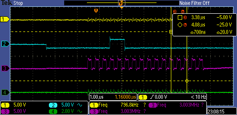
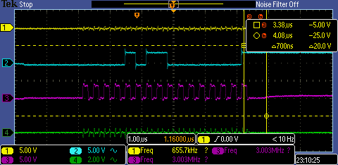
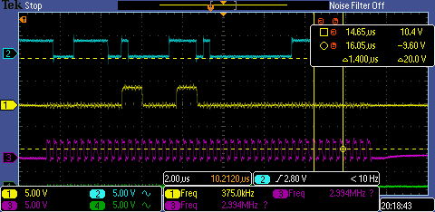
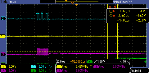
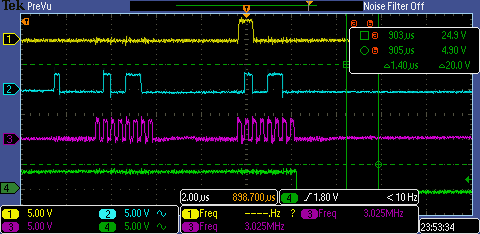
First I am testing the RFID with a close tag to it and I am trying to read it, see the image bellow.

But as before the Iso14443a_PollingCommand isn't end properly.

I am calling the Iso14443a_PollingCommand 5 times max if it returns STATUS_FAIL.

the following sequence happen always :

1. At the first call of the Iso14443a_PollingCommand the TRF7970A triggers an interrupt with pui8_IrqStatus == 0xC0 = PROTOCOL_ERROR.

2. As a result the Trf797xIrqWaitTimeout  set the g_sTrf797xStatus to TX_ERROR and return.

3. At the second call of the Iso14443a_PollingCommand  ( because the first one failed)  the TRF7970A  triggers an interrupt with pui8_IrqStatus == 0x80 = TX_COMPLETE

4. At this stage the Trf797xIrqWaitTimeout function works properly, waited for TX_COMPLETE and moves on to wait for RX_COMPLETE 

5. At this stage I am waiting for IRQ with IRQStatus == 0x40 = RX_COMPLETE but the TRF7970A  not triggering any interrupt.

6. the Trf797xIrqWaitTimeout  sets the g_sTrf797xStatus = NO_RESPONSE_RECEIVED cause there is no IRQ from the TRF7970A , no matter how much time I am waiting( tried to wait until the g_ui8IrqFlag is high without a timeout)

7. This is repeated as long as I call again and again the Iso14443a_PollingCommand .

Need your help please

Best Regards

Jawad Khaleel

  • Hello Jawad,

    There seems to be timing issues with your application code and how it handles the IRQ interrupts.

    If you receive an IRQ of 0xC0, then that would indicate that the IRQ interrupts are not being serviced promptly. Timing is very important for the TRF7970A and all interrupts have to serviced with high priority.

    Section 4.6 of our device FAQ outlines the issue with getting a 0xC0 IRQ status: http://www.ti.com/lit/pdf/sloa246

    When you repeat the cycle and get a NO_RESPONSE_RECEIVED that means that the tag did not reply in time, which it might be stuck in a state waiting for a different command if you never replied to the first attempt it had at communication when you did not handle the 0xC0 properly. So please address the reception of 0xC0.

  • Hello Ralph,

    thanks for your reply.

    I already read Section 4.6 of your device FAQ outlines the issue with getting a 0xC0 IRQ status.

    But this didn't help me much !.

    my MCU runs in 168 MHz ( thinks that is enough), ( tried to use 480 MHz but it didn't solve the problem.)

    my SPI Baud Rate is 3MBits/s.( tried from 1.5 to 3 MBits/s)

    I gave the IRQ pin the highest priority ( priority = 1) , this way I do not miss the interrupt.

    I reset the FIFO with 0x0F direct command every time I got an interrupt, even tried to add it also before the Iso14443a_PollingCommand   but this didn't solve the 0xC0 issue.

    So I got the interrupt fast because the interrupt has the highest priority, and I reset the FIFO every time it needed but still I got  0xC0 as IRQ status.

    What you think that I am doing wrong !?

    Please I need you help.

    Best regards

    Jawad Khaleel

  • Hello Jawad,

    Can you get a logic state analyzer and scope out all the SPI lines + IRQ for the duration of device start-up until it hits the error case?

    Specifically I need a waveform with precise (ms minimum, us preferred) timing between each SPI command in order to see the order of the commands, when IRQ triggers, and what flags are being read by the MCU.

    Saleae offers a good solution for this if you don't have one in house.

  • Hi Ralph,

    Thank you again for your assistance.

    I don't have a logic state analyzer instead I have a regular scope where I captured all the SPI lines plus the IRQ line as shown below.

    SPI MISO is the yellow line.

    SPI MOSI is the blue line.

    SPI SCK is the purple line.

    IRQ is the green line.

    the commands sent as described below.

    1. I supply the VIN, SS, EN2, EN as described on the data sheet.

    2. To check the SPI connection:

    2.1. I send the SOFT_INIT (0x03) command, so 0x83 is sent to the TRF7970A

    2.2 I send the IDLE_Command (0x00), so 0x80 is sent to the  TRF7970A

    2.3 I perform the read register single command on the TRF797x_MODULATOR_CONTROL

    so 0x49  is sent to the  TRF7970A

    and receive one byte as expected MODULATOR_CONTROL_VALUE_AFTER_SOFT_INIT (0x91)

    3. Trf797xInitialSettings:

    3.1 send TRFTRSET (0x0F) direcet command

    so 0x8F is sent to the  TRF7970A

    3.2 update the TRF797x_MODULATOR_CONTROL value to 0x01

    so 0x0901 is sent to the  TRF7970A

    3.3 update the TRF797x_NFC_TARGET_LEVEL value to 0x00

    so 0x1800 is sent to the  TRF7970A

    3.4 update the TRF797x_REGULATOR_CONTROL to 0x01 as you recommended in the previous thread 

    so 0x0B01 is sent to the  TRF7970A

    4. Nfc_Iso14443a_Read:

    4.1 update the TRF797x_STATUS_CONTROL value to 0x21

    so 0x0021 is sent to the  TRF7970A

    4.2 Trf797xWriteInitiatorSetup(0x88)

    4.2.1 update the TRF797x_ISO_CONTROL value to 0x88

    so 0x0188 is sent to the  TRF7970A

    4.2.2 update the TRF797x_MODULATOR_CONTROL value to 0x01

    so 0x0901 is sent to the  TRF7970A

    4.2.3 update the TRF797x_FIFO_IRQ_LEVELS value to 0x0C

    so 0x140C is sent to the  TRF7970A

    4.3 Iso14443a_TagSelection(REQA)

    4.3.1 Iso14443a_PollingCommand(ui8Command)

    I send the buffer below by SPI

    g_ui8TrfBuffer[0] = 0x8F; // Reset FIFO
    g_ui8TrfBuffer[1] = 0x90; // Send without CRC
    g_ui8TrfBuffer[2] = 0x3D; // Write Continuous
    g_ui8TrfBuffer[3] = 0x00; // Length of packet in bytes - upper and middle nibbles of transmit byte length
    g_ui8TrfBuffer[4] = 0x0F; // Length of packet in bytes - lower and broken nibbles of transmit byte length
    g_ui8TrfBuffer[5] = 0x26; // Send the polling command from function input - either REQA (0x26) or WUPA (0x52)

    5. here we can see the interrupt pin rise after the polling command

    this command sent to the TRF7970A is the same command in 4.3.1

    you can see that the interrupt rises after 90-96 us from the polling command

    6. here you can see that the interrupt rise for 900 us and get low again

    this command sent to the TRF7970A is the same command in 4.3.1

    7. this is a closer look on the falling of the interrupt line on 6

    here you can see the 0xC0 I get when I read the IRQ register ....

    there is no two interrupts where I miss the first one !

    Is the 900us rising duration is proper? and the rising time 96us after the polling command is proper?

    Best Regards

    Jawad Khaleel

  • Hello Jawad,

    The point here is that you aren't missing an IRQ but that you are not servicing the first one promptly enough and these captures make that very clear.

    jawad khaleel said:
    and the rising time 96us after the polling command is proper?

    Yes.

    jawad khaleel said:
    Is the 900us rising duration is proper?

    Not even close, this is incredibly slow and is the root cause. You are not reading the IRQ promptly. Typical IRQ high times should be sub 30 us. The moment IRQ is received the MCU should IMMEDIATELY read the IRQ register to get the status which clears IRQ.

    By waiting so long, the RX already started before TX has been registered and therefore you may get corrupted data as the FIFO has not been reset. For this reason the firmware will treat this an error case and stop communication there to be restarted.

  • Hi Ralph,

    this is my Trf797xIRQ function :

    void Trf797xIRQ(void)							// interrupt handler
    {  
    	uint8_t ui8IrqStatus, ui8IsoControl;
    	g_ui8IrqFlag = 0x01;
    
    	do
    	{  
    		// IRQ status register has to be read
    		Trf797xReadIrqStatus(&ui8IrqStatus);
    
    		if(ui8IrqStatus == 0xA0)				// TX active and only 3 bytes left in FIFO
    		{
    			g_sTrf797xStatus = TX_WAIT;
    			break;
    		}
    		else
    		{
    			ui8IsoControl = TRF797x_ISO_CONTROL;
    			Trf797xReadSingle(&ui8IsoControl);
    			if((ui8IsoControl & BIT5) != BIT5)			// RFID mode
    			{
    				Trf797xISR(&ui8IrqStatus);
    			}
    			else										// NFC mode
    			{
    				// Do Nothing
    			}
    		}
        }while(HAL_GPIO_ReadPin(RFID_IRQ_GPIO_Port, RFID_IRQ_Pin) == GPIO_PIN_SET);  
    }

    Since I gave this interrupt pin the highest priority the interrupt starts immediately.
    Could it be that the MCU is so fast and reads again and again the ui8IrqStatus before the TRF7970A can lower tthe IRQ pin !?

    Best Regards
    Jawad Khaleel

  • Hello Jawad,

    I am not familiar with your MCU but it is very clear that it is not triggering the interrupt at the priority you are expecting.

    https://e2e.ti.com/cfs-file/__key/communityserver-discussions-components-files/667/TEK00015.PNG

    Look at that image - no reads of IRQ status occur until you get the 0xC0. There is no way the MCU is reading it like you are describing.

    You need to work the MCU support team to understand why your IRQ read is so slow. I cannot help with that.

  • Hello Ralph,

    First I want to thank you for your help.

    Now I manage to get TX_COMPLETE and RX_COMPLETE separatly after the Iso14443a_PollingCommand , but after the RX_COMPLETE I got another interrupt with

     g_sTrf797xStatus = NO_RESPONSE_RECEIVED;

    this interrupt cause the Iso14443a_PollingCommand to return STATUS_FAIL at the end.

    what the interrupt with status NO_RESPONSE_RECEIVED mean !? if the TX_COMPLETE  and the RX_COMPLETE  received?

    Is disabling the interrupt pin after receiving the RX_COMPLETE is an option ? or still I need to return from Iso14443a_PollingCommand before this third interrupt ?

    Or maybe there is another way to band the TRF7970A to send interrupt with no response ?

    Best Regards

    Jawad Khaleel

  • Hello Jawad,

    NFC requires precise timing between packets. If a tag does not reply in time based on the spec, then the NO_RESPONSE_RECEIVED status is triggered.

    NO_RESPONSE_RECEIVED actually means no IRQ was received. There is a timeout associated with every transmission and if the timeout occurs before the IRQ then the NO_RESPONSE_RECEIVED status is set.

    One thing you should look at is if the timeout is occurring correctly. When porting, sometimes the timeouts aren't handled right. You probably will want to toggle and monitor GPIO to verify that the RX timeout occurs correctly (so raise a pin when starting the RX Timeout and drop it when it is done).