

Other Parts Discussed in Thread: CC1352P
Hi!
It's me again. As I said in other posts, I am designing a CC2652P based hardware. As there is no reference design for this IC provided by TI, I have been using LAUNCHXL-CC1352P-2 reference design (swrc350a) both for firmware and hardware.
At the moment, I have 4 main questions:
1- About the antenna switch SKY13317-373. I am aware that CC1352P provides also sub-1GHz communication so it needs to switch if using a double antenna. This is not the case of CC2652P. However, I have seen that in order to use 20dBm output I must switch TX and RX because it uses one-way transmission lines (TX_20DBM_P and TX_20DBM_N for TX; RF_P and RF_N for RX). My question is, do I still need to use SKY13317-373 (grounding pin 6 of it) or can I solve this other way? And what about the switching, is it solved by TI driver in firmware just by doing this (see image)?

2- In CC1352P design, it says that Z60 is optimized for 868/915 MHz and OK performance at 2.44 GHz. In this case, I need it to be optimized for 2.4Ghz only (I will use SWRU120D 2.4-GHz Inverted F Antenna). What value should I use?
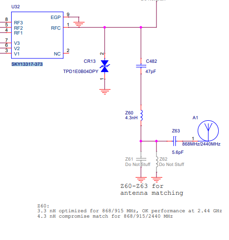
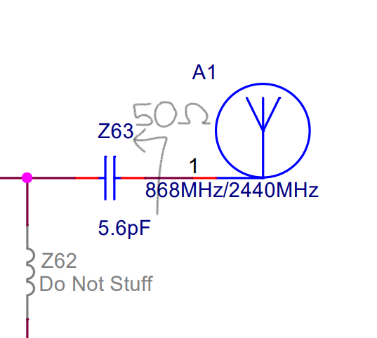
3- About matching impedance. In this picture, is impedance 50ohm? I need to confirm it in order to calculate match impedance for my custom design.
4- Finally, about RF_TX signal. I see that it is located in 2_4_GHZ_RF_P and SUB-1_GHZ_RF_P nets. In my design, should I keep it only in RF_P or also in TX_20DBM_P?
Any other advice or document regarding CC2652P design would be welcome.
Thanks!!
