This thread has been locked.

If you have a related question, please click the "Ask a related question" button in the top right corner. The newly created question will be automatically linked to this question.

TRF7970A: TRF7970A EVM Hardware - VDD_X regulator supply generation

Part Number: TRF7970A
Other Parts Discussed in Thread: MSP430F2370

Hi,

I am working on TRF7970A EVM with DM0 Mifare classic sample application. By reading the TRF7970A datasheet, what I understand is, VDD_X will be generated only when (EN=0 & EN2=1) or (EN=1 & EN2=X) but not when (EN=0 & EN2=0). 

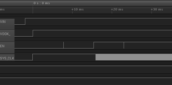
In the TRF7970A EVM, the EN2 is connected to GND and EN is controlled by MSP430F2370. When the TRF7970A EVM is connected to the USB port, VIN is available and (EN=0 & EN2=0). After 2ms delay from VIN, the VDD_X regulated supply is generated. However, the EN and EN2 are still LOW. I could see that SYS_CLK is generated only when EN=1.  Please refer the below image.

I could not understand how the VDD_X regulated supply is generated and the MSP430 is powered ON while (EN=0 & EN2=0) when the TRF7970A EVM is connected to the USB port.

Can anyone explain this please?

Thanks and Regards,

Sunil

  • Hello Sunil,

    after digging into the schematic of the EVM I have to confess, that in this configuration with EN2 = 0, the system starts only due to parasitic effects.

    After some measurements it turned out that the MSP generates, after USB power up, its supply voltage from the signals applied (TX, RX from USB to serial converter). This leads to a MSP supply voltage of ~2V which was enough to start the TRF7970A.

    In a circuit like that the EN2 pin has to be set to "1" to guarantee a save startup or a different supply circuitry has to be implemented.

    Best regards,

    Helfried 

  • Hi Helfried,

    I understand that EN2 is supposed to be connected to VIN in TRF7970A EVM. Thanks, I will consider this in my design.

    However, I am not clear on how MSP could generate DVcc/AVcc from the TX, RX signals from CP2102 IC. Please explain if possible.

    Best Regards,

    Sunil

  • Hello Sunil,

    sorry for the late answer. Your asked about how the MSP can get his VCC from an input signal. This is due to the internal ESD diode that is at the input pin connected to VCC.

    Any high level at an input pin can bring the VCC to a voltage level Vin - Vdiode, but this will work only when the signal is able to deliver enough current.

    Best regards,

    Helfried