This thread has been locked.

If you have a related question, please click the "Ask a related question" button in the top right corner. The newly created question will be automatically linked to this question.

CCS/DLP-7970ABP: MSP432P401R + DLP7970ABP, Need to power the boosterpack with 5V to extend read range. How?

Part Number: DLP-7970ABP
Other Parts Discussed in Thread: TRF7970A

Tool/software: Code Composer Studio

Hi,

I would like to have a 5V power supply for the DLP7970ABP with the MSP432P401R, in order to have a larger dynamic range in the RSSI values obtained.

I have already enabled the byte: 5V_suply = true; inside the TRF7970A settings. I am using the built in USB for getting the power and also tx/rx commands via UART. I would like to maintain that connection.

My question is: how to wire the boosterpack to 5V, since the pin of 5V is empty and does not map with any pin of the header? Some help?

Thank you.

  • Hello Daniel,

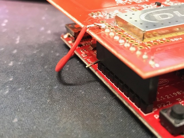
    You'd have to bend the 3.3V input wire on the LaunchPad so it doesn't go into the BoosterPack header and then route a wire with 5V up to the BoosterPack pin. That's the only way unfortunately.

    The LaunchPad pins are somewhat durable but they don't always take well to being bent so far over, so you would need to be prepared that the change may end up being a permanent alteration to the LaunchPad.

    This is how it looked on a different LaunchPad (We had to tap into USB power on that one since it didn't have a 5V pin):

  • Hi,

    Thanks for the quick answer.

    Okay, so the wire is welded to the pin 1 of the DLP, but the other end... is welded directly to a power supply for an smartphone, for example? Or has to be welded to the 5V pin in the MSP432? I suppose that also the ground has to be welded?

    Thank you. 

    PD: I have MSP432P401R Rev 2.1 and DLP7970ABP v4.5 

  • Hello Daniel,

    That wire was soldered to a 5V supply on that board. For that specific LaunchPad, it did not have a 5V pin available for BoosterPack's. With the MSP432 LaunchPad, you can just solder to the 5V pin available on the board.

    No need to mess with ground, that connection is done on the other side of the BoosterPack headers.