This thread has been locked.

If you have a related question, please click the "Ask a related question" button in the top right corner. The newly created question will be automatically linked to this question.

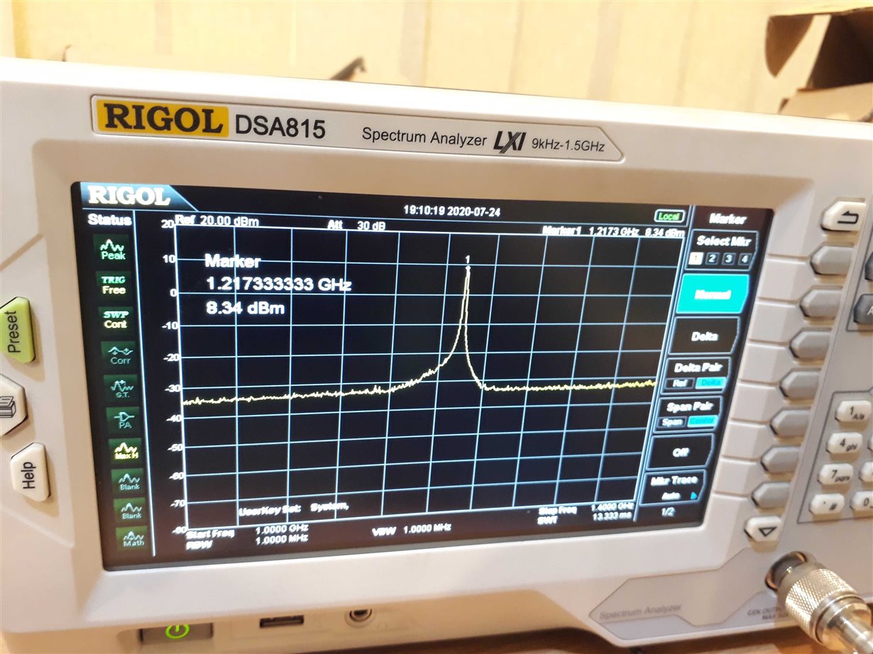
CC2500: CC2592 and CC2500 design : 1.2Ghz Half harmonic seen at 2.4GHz output

Part Number: CC2500
Other Parts Discussed in Thread: CC2591, , CC2592

Hi,

We have developed a board using cc2500 transceiver with cc2591 range extender and a SMA connector for antenna. We have followed the reference designs that we given on the website for the transceiver and the range extender as closely as possible. The issue we are observing is that during transmission there is half harmonic of 2.4Ghz carrier frequency present. The power is set at 14dbm. Please see the below spectrum analyzer capture

We had made two different batch of boards using the same design over a couple of months period. This issue was observed in the boards from second batch.

What are the possible causes of this? Any help would be really appreciated.

Thanks.

Regards,

Hur Haider

  • Hi,

    A half harmonic is an indication that the design is close to unstable.I would recommend to use a slide tuner or similar and check the performance of the design when the load is not perfect 50 ohm

    CC2591 is not recommended for new designs, CC2592 should be used instead. A design based on CC2592 is easier to get stable than a design based on CC2591

  • Thanks for the feedback points. The design that we have made is actually using the cc2592 (cc2591 was a typo) and we used the reference design for it.Please see below snapshots of the schematics that we made

    Can you please take a look at these and guide us about what component(s) is causing this issue and what changes can be made to resolve it. We can also share the gerber files for further analysis if you need them. 

    Thanks.

    Regards,

    Hur Haider

  • Pleas use the "insert/ Edit Media" when you are trying to include pictures since what you have tried to include is not visible in your post. 

  • Sorry about that. Please see the captures below:

    Thanks.

    Regards,

    Hur Haider

  • - Do you have access to a slide tuner to do a simplified load pull? 

    - Have you tried to measure the output of C49 with U51 removed? 

    - Do all boards from the same batch behave the same way? Meaning that all boards from the first batch looks good and all from the second batch have the unwanted tone? 

  • Please see the answers below:

    No. we do not have the slide tuner available to us.

    We have not tried to measure the output of C49 with U51 removed since the U51 has been there since the beginning of the design. Do you think that it may be the cause of this?

    Yes, the boards from the first batch behave the same way. We observed this issue on the second batch of boards that we received.

    Thanks

    GPS_PROG_EN

  • As I wrote I suspect that your design is marginally stable. Meaning that a small change could cause the design to be stable (in 50 ohm) or not. It could be that the substrate and/ or the board thickness are slightly different between the two batches. 

    In my opinion a load pull should always be done on boards using a FEM to ensure that the design is stable for the wanted region of the smith chart. 

    Could you also post a layout plot?

    Why do you need a TCXO for a 2.4 GHz product? 

  • Thank you for the pointers.

    We used TCXO for a a stable frequency over temperature range (-40C to 85C)

    Regarding the layout gerber files can I please send them to you through email?

  • Send me a friend request here on the forum and when I accept the request you will be able to send me a private message with the files.