This thread has been locked.

If you have a related question, please click the "Ask a related question" button in the top right corner. The newly created question will be automatically linked to this question.

CC1125: register configuration

Part Number: CC1125
Other Parts Discussed in Thread: CC-DEBUGGER

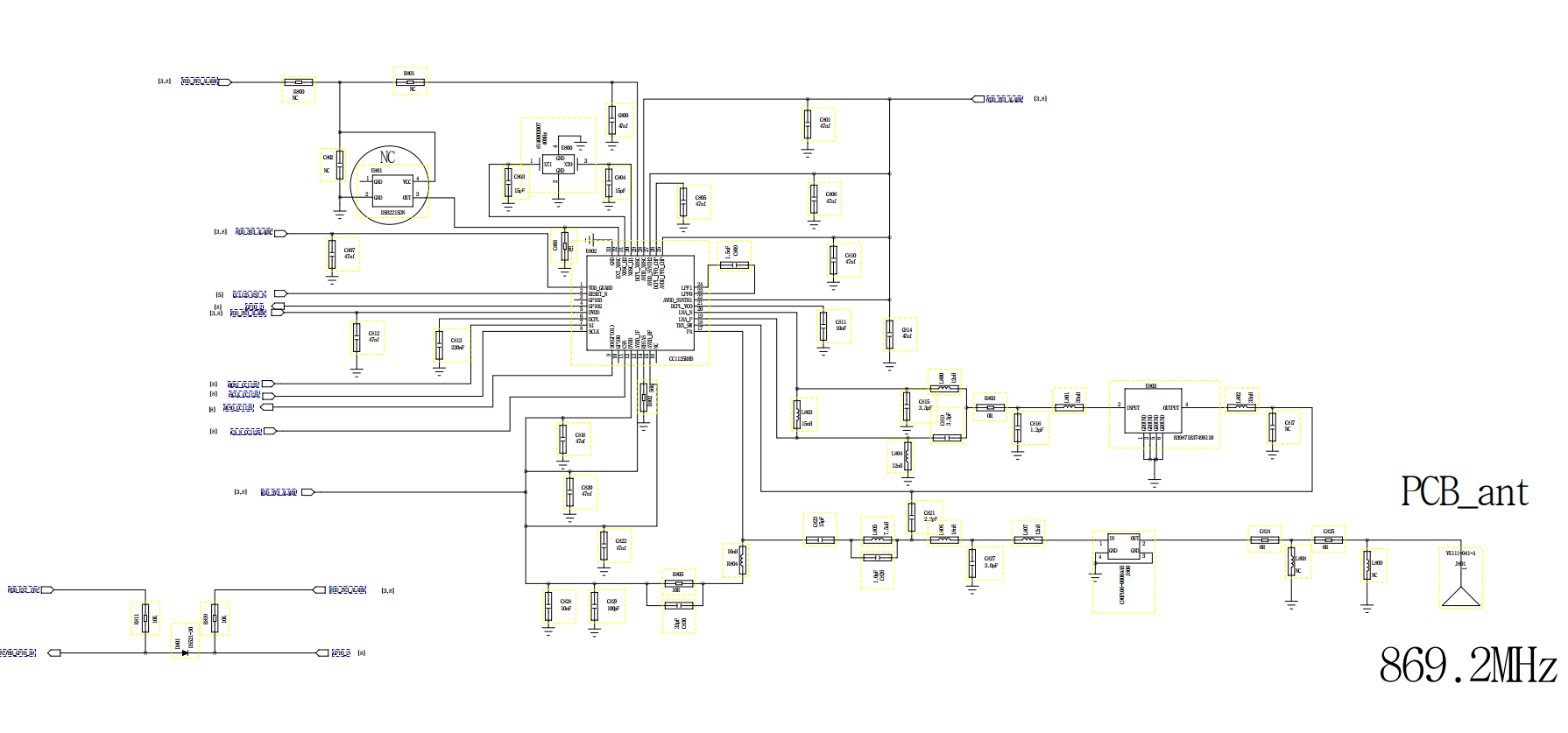
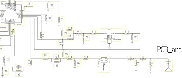
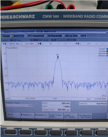
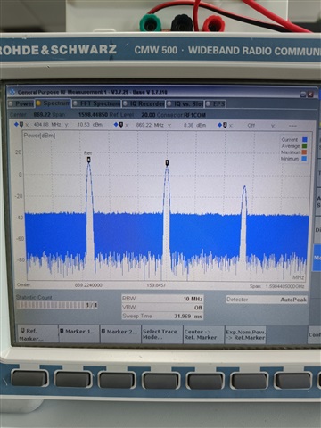
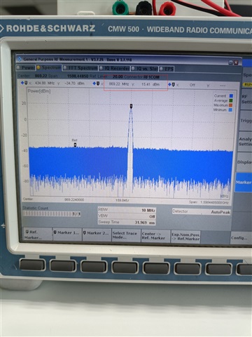
we do RF test for CC1125 , chip out of the maximum power is only about 7dBm (we set 15dBm),

now we doubt register configuration problem, need help to analyze

  • Hi Jimmy,

    OK. Something is wrong here when missing approx 8 dB.

    Can you send your schematic ?

    Have you tested with a static tx in Smart RF studio with your hardware ?

  • Smart RF is not supported for testing in this project. It can only be set by sending commands(CMD). The commands sent are as follows:

    insmod /lib/modules/3.18.48/extra/cc1125.ko

    cd /sys/bus/spi/devices/spi1.0/


    echo "43" > read && dmesg -c

     /*Set frequency*/

    echo "12044 86" > write && dmesg -c

    echo "12045 236" > write && dmesg -c

    echo "12046 40" > write && dmesg -c

    echo "12049 5" > write && dmesg -c


    /*Set modulation mode 2-GFSK*/

    echo "11 10" > write && dmesg -c


    /*set power 15dBm*/

    echo "43 127" > write && dmesg -c


    /*Enable TX*/

    echo "53" > cmd && dmesg -c

    schematic diagram:

    Schematic diagram (partial)

    PCB:

    Test results:

  • Hi,

    I'm not familiar with the uSMA you are using on your board. Is the antenna section disconnected when you are measuring the conducted output power?

    C809 should be 1.8 nF for CC1125

  • hello,When measuring the conducted output power, the antenna is disconnected and measured directly at the output port of the chip, the result is still 8dbm.

  • HI Jimmy,

    Still recommend to connect the CC1125 to a CC-debugger so the unit can be controlled via SmartRF studio. In order to test the hardware with a known software test suite

    The schematic values looks fine.

    Are you using 0201 or 0402 ?

    Do you have the pcb-stackup as well ?

    Regards,

       Richard

  • Hi,

    Can you also read from the register PA_CFG2 just to confirm that the power setting has been set correctly ?

  • Hi,

    How can CC1125 on our board connect to smartRF studio? At present, the USB can't recognize the connecting; Finally, we have to use our own software to control cc1125, so we need to make clear for the specific register configuration.

    We use 0201

    PCB 6 layers, RF is on the bottom layer 

    PA_ CFG2 is configured as 0x7F, max power

  • If the RF is on layer 6, is layer 5 a GND layer ?

    What is the thickness of the pre-preg between layer 5 and 6 ?

  • Hi RGW

    My client needs to know how his board can connect smartRF studio and what is the correct register configuration first. So would you please reply to this question first?Thank you.

    My client now suspects that maybe the register configuration problem is wrong, because now he tests his board, the base wave is like 434.88mhz, as shown in the following figure.

    When testing Ti demo board,it is normal.

  • Ideal if you can connect the customer's hardware to a CC-Debugger.

    More info on how to connect : https://www.ti.com/lit/swru197