This thread has been locked.

If you have a related question, please click the "Ask a related question" button in the top right corner. The newly created question will be automatically linked to this question.

CC1101: Balance Antenna

Part Number: CC1101

Is it possible to use a balance antenna with the CC1101 ? how ?

There is a lot of documentation about connecting the cc1101 to a unbalanced antenna through a balun , but there is no documentation on how to connect a balanced antenna.

I have designed a balanced antenna for the ISM Band (433.05 MHz 434.79 MHz) and tried connected it directly, total failure.

Then I tried match the cc1101 with the antenna with differential network, the cc1101 has an impedance of 116 + j41 @ 433Mhz (sourde datasheet), the matching network result in something like this: 
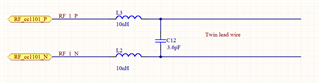
Also failed.

BUT, the same antenna through a balun (0433BM15A0001), works perfectly.

Any ideas on how can I remove the balun ? is  that even possible ?

Thanks

  • Hi Carlos,

    We stopped making balanced antenna reference design to the chips approximately 12 years ago since these were difficult for the customers to replicate exactly. If the customer used a slightly different stack-up, the design needed to be re-simulated and this was not practical for the broad market support.

    It is possible to remove the balun but I would not recommend it. You will only save 4 passive components in the balun so the cost advantages are limited especially when the design time will be increased and more complex.

    What is the motivation to remove the balun ?

  • HI RGW.

    Long story short, I do not have enough space on the pcb for a 433Mhz antenna (or ground plane big enough for that wave length ).

    In my use case , I do not need to cover a great distance but I need to cover the whole frequency range (433.05 MHz-434.79 MHz), so I came up with a loop-balanced antenna design as a solution, so I could make it work in a small ground plane.

    The antenna works fine, but trying to connect to the cc1101 I had the problem I have described.

    After some try & error I find out that the antenna works with the balun ( but I do not understand why and I would like to understand why).

    On the other hand, as you said I would like to remove the balun, this is my first revision, but  in a long term I will need to use use 2 frequencies 433Mhz and 868Mhz, in that case, I would need 2 baluns, 2 matching networks and a rf switch, I would like to keep this simple and use only 1 matching network / balun. I think this would be easier( correct me if I am wrong).

    I understand , that removing the balun or moving away from the "normal designs" is gonna be difficult in terms of antenna design and matching network, but I think I do not have other way because of my requirements.

    Looking forward for your comments.

  • Hi,

    If you have a compact design, then using a dipole topology or balanced antenna is not the best way to go since this will require more physical space than a standard monopole solution. An advantage of monopole antennas, is that you are using the GND plane as one antenna element which helps to reduce the overall size.

    If you want to cover both 433 MHz and 868 MHz, then I would use one balun targeted around 868 MHz and this will still work at 433 MHz but will higher losses. The higher losses at 433MHz should be OK since the 433 MHz is a lower power band anyway so this should be acceptable.

    Then you will need a SPDT switch to branch into two LPF filters, one for 868 MHz and the other for 433 MHz. 

    You could use two antennas or combine the two LPFs back into a common port again with another SPDT; and then use a dual-band antenna. 

    What is the size of your board ?

    Regards,

       Richard 

  • Hi, thanks for your comments.

    Let explain more details, I have not explained it very clearly, my bad.

    The antenna that I am using ( loop balanced antenna) is external to my PCB, no size problem here.

    The size of my PCB is 50mmx55mm. ( wave length for 434Mhz=69cm, wl/4 => 17.25cm, way to long for my  ground plane) 

    If I need to use a RF switch anyway, I would prefer to use 2 baluns and a dual band antenna ( each balun with their own marching filter ), Any thoughts on this?

    But I will try the 868Mhz balun on 433Mhz, definitely is a good idea.

    Coming back to the no-balun issue, I think my problem could be the common mode noise I found this nice picture explaining it

    What do you think?

    My idea for my first version (only 433mhz) is :

    CC1101 =>>> 433Mhz Balun =>> coax cable =>> Balanced loop antenna.

    Looking forward for your comments.

  • Just make sure you do not have any spurious emissions especially at the harmonic frequencies that exceed regulatory limits.

  • HI RGW, sorry but before closing the issue, I would like to double check some points:

    1.- Because the size of the pcb, I need a balanced antenna

    2.- I need a balun for the balanced antenna because the common noise. Do you think this could be the reason why the cc1101 does not work without the balun ?

    3.- There is no problem connecting the external balanced antenna, with a balun and a coaxial cable.

    4.- For the future revision , I will need a rf switch to match the antenna(s) at 433mhz and 868mhz, with 2 baluns and 2 matching networks, or 1 balun (868 mhz ) and 2 matching networks. Which option do you think it the best ?

    Sorry for not closing the issue straight forward but I need to be sure of these points.

    Bests Regards

  • Hi,

    1. The size of the PCB does not motivate usage of a balanced antenna. 

    2. A balun is not necessary because of the common noise. We have used balanced topologies previously but do not use these any more since they are more complicated to support for the mass-market. Please see below as an example of a balanced design at 915 MHz:

    As can be seen in the design a balun is not used.

    3. Some dipole antennas, have a coaxial-balun inbuilt (Bazooka Balun). Are you sure that this is not the case here ?

    More info on this can be found at : https://www.antenna-theory.com/definitions/balun.php

    4. 1 balun (868 MHz) with 2 matching /LPF networks will be the best solution

    Best regards,

       Richard