Other Parts Discussed in Thread: CC1101
Hi there,
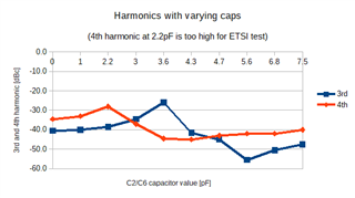
Our radio system did not pass the ETSI EN 300 220 test due to harmonics i.e. the 4th harmonic at 3472MHz is too high.
If I measure harmonics by cable, everything is fine and the band-pass filter as proposed in the datasheet schematics does its job well. But if I measure via our antenna, harmonics get higher. I assume this is because the antenna and its impedance matching are not 50Ohm at 3472MHz (but they are 50Ohm at 868MHz of course). I was not successful to change the band-pass filter for any harmonics improvement.
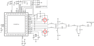
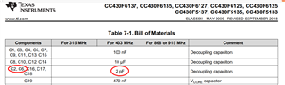
However. I found that if I increase the values of those low-value decoupling caps C2/C6 (see schematics in datasheet from sept 2018 on pages 110-111) harmonics get much better. Ideal value I found is 4.7pF (see graphic below for measured harmonics vs. capacitor value).
But these caps are proposed to be 2.0pF !! It seems to me, that this is a rather low value in the range of PCB parasitics. Unfortunately, I could not find any layout proposal for the CC430. Just for CC1101 which is a bit different package and pinout compared to CC430.
So, now my question: What if I increase these capacitor values from 2pF to 4.7pF? Could there be any bad side effects?
Thank you
A few more background informations:
- We were using the CC430 succesfully for years now. I had to do some design changes on one of our products, which obviously caused higher harmonics. If possible we do not want to change the layout again but decrese the harmonics by changing the assembly.
- RF Layout practices were considered as far as compromises allowed: Caps as close to IC as possible, GND plane on layer below, 50Ohm RF line... etc...
- We are using high frequency capacitors (Johanson S-Series)