This thread has been locked.

If you have a related question, please click the "Ask a related question" button in the top right corner. The newly created question will be automatically linked to this question.

CC1310: CC1310 Adjacent channel power issue

Part Number: CC1310

Dears

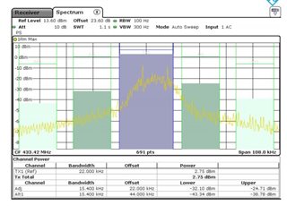
During the GS529p07 & P08 EMC test, the customer found that: adjacent channel power.

Please help check whether there are configuration and PCB problems. Thank you very much!

Design application: smoke alarm

PN:CC1310

CC1310 Adjacent channel power issue by 433MHZ

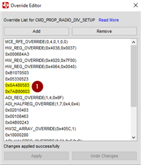
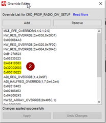
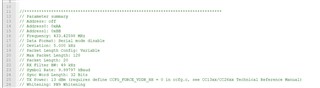
The following is our software configuration:
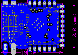
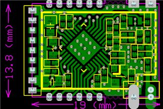
pcblayout a and b

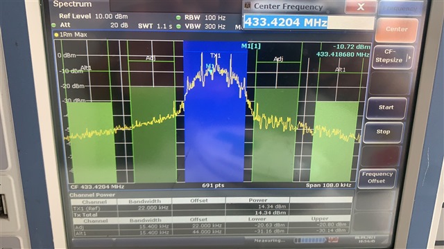
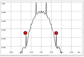
GS529-P07 Waveform&Report:

NC letter report (2020-3-10)--EMC format GFT-OP-10a Letter Report_GZ.pdf

  • Hi, 

    Wich PHY in SmartRF Studio have you used? 5 kbps SimpleLink Long Range? Please share your smartrf_settings.c file with us.

    -Simon 

  • Hi Simon

    FYI

    1727.smartrf_settings.c
    //*********************************************************************************
    // These settings have been generated for use with TI-RTOS and cc13xxware
    //
    // Generated by SmartRF Studio version 2.6.1 (build #20)
    // Tested for TI-RTOS version tirtos_simplelink_2_21_00
    // Device: CC1310 Rev. 2.1
    // 
    //*********************************************************************************
    
    
    //*********************************************************************************
    // Parameter summary
    // Address: off 
    // Address0: 0xAA 
    // Address1: 0xBB 
    // Frequency: 433.42598 MHz
    // Data Format: Serial mode disable 
    // Deviation: 5.000 kHz
    // Packet Length Config: Variable 
    // Max Packet Length: 128 
    // Packet Length: 20 
    // RX Filter BW: 49 kHz
    // Symbol Rate: 9.99797 kBaud
    // Sync Word Length: 32 Bits 
    // TX Power: 13 dBm (requires define CCFG_FORCE_VDDR_HH = 0 in ccfg.c, see CC13xx/CC26xx Technical Reference Manual)
    // Whitening: PN9 Whitening 
    
    #include <driverlib/rf_mailbox.h>
    #include <driverlib/rf_common_cmd.h>
    #include <driverlib/rf_prop_cmd.h>
    #include <ti/drivers/rf/RF.h>
    #include <rf_patches/rf_patch_cpe_genfsk.h>
    #include <rf_patches/rf_patch_rfe_genfsk.h>
    #include "smartrf_settings.h"
    
    
    // TI-RTOS RF Mode Object
    RF_Mode RF_prop =
    {
        .rfMode = RF_MODE_PROPRIETARY_SUB_1,
        .cpePatchFxn = &rf_patch_cpe_genfsk,
        .mcePatchFxn = 0,
        .rfePatchFxn = &rf_patch_rfe_genfsk,
    };
    
    // Overrides for CMD_PROP_RADIO_DIV_SETUP
    static uint32_t pOverrides[] =
    {
        // override_use_patch_prop_genfsk.xml
        // PHY: Use MCE ROM bank 4, RFE RAM patch
        MCE_RFE_OVERRIDE(0,4,0,1,0,0),
        // override_synth_prop_430_510_div10.xml
        // Synth: Set recommended RTRIM to 7
        HW_REG_OVERRIDE(0x4038,0x0037),
        // Synth: Set Fref to 4 MHz
        (uint32_t)0x000684A3,
        // Synth: Configure fine calibration setting
        HW_REG_OVERRIDE(0x4020,0x7F00),
        // Synth: Configure fine calibration setting
        HW_REG_OVERRIDE(0x4064,0x0040),
        // Synth: Configure fine calibration setting
        (uint32_t)0xB1070503,
        // Synth: Configure fine calibration setting
        (uint32_t)0x05330523,
        // Synth: Set loop bandwidth after lock to 20 kHz
        (uint32_t)0x0A480583,
        // Synth: Set loop bandwidth after lock to 20 kHz
        (uint32_t)0x7AB80603,
        // Synth: Configure VCO LDO (in ADI1, set VCOLDOCFG=0x9F to use voltage input reference)
        ADI_REG_OVERRIDE(1,4,0x9F),
        // Synth: Configure synth LDO (in ADI1, set SLDOCTL0.COMP_CAP=1)
        ADI_HALFREG_OVERRIDE(1,7,0x4,0x4),
        // Synth: Use 24 MHz XOSC as synth clock, enable extra PLL filtering
        (uint32_t)0x02010403,
        // Synth: Configure extra PLL filtering
        (uint32_t)0x00108463,
        // Synth: Increase synth programming timeout (0x04B0 RAT ticks = 300 us)
        (uint32_t)0x04B00243,
        // override_synth_disable_bias_div10.xml
        // Synth: Set divider bias to disabled
        HW32_ARRAY_OVERRIDE(0x405C,1),
        // Synth: Set divider bias to disabled (specific for loDivider=10)
        (uint32_t)0x18000280,
        // override_phy_rx_aaf_bw_0xd.xml
        // Rx: Set anti-aliasing filter bandwidth to 0xD (in ADI0, set IFAMPCTL3[7:4]=0xD)
        ADI_HALFREG_OVERRIDE(0,61,0xF,0xD),
        // override_phy_gfsk_rx.xml
        // Rx: Set LNA bias current trim offset to 3
        (uint32_t)0x00038883,
        // Rx: Freeze RSSI on sync found event
        HW_REG_OVERRIDE(0x6084,0x35F1),
        // override_phy_gfsk_pa_ramp_agc_reflevel_0x1a.xml
        // Tx: Configure PA ramping setting (0x41). Rx: Set AGC reference level to 0x1A.
        HW_REG_OVERRIDE(0x6088,0x411A),
        // Tx: Configure PA ramping setting
        HW_REG_OVERRIDE(0x608C,0x8213),
        // override_phy_rx_rssi_offset_neg2db.xml
        (uint32_t)0x000288A3,
        HW32_ARRAY_OVERRIDE(0x2000,1),
        (uint32_t)0x22000000,
        (uint32_t)0x540001E3,
        (uint32_t)0xFFFFFFFF,
    };
    
    
    // CMD_PROP_RADIO_DIV_SETUP
    // Proprietary Mode Radio Setup Command for All Frequency Bands
    rfc_CMD_PROP_RADIO_DIV_SETUP_t RF_cmdPropRadioDivSetup =
    {
        .commandNo = 0x3807,
        .status = 0x0000,
        .pNextOp = 0, // INSERT APPLICABLE POINTER: (uint8_t*)&xxx
        .startTime = 0x00000000,
        .startTrigger.triggerType = 0x0,
        .startTrigger.bEnaCmd = 0x0,
        .startTrigger.triggerNo = 0x0,
        .startTrigger.pastTrig = 0x0,
        .condition.rule = 0x1,
        .condition.nSkip = 0x0,
        .modulation.modType = 0x1,
        .modulation.deviation = 0x14,
        .symbolRate.preScale = 0xB,
        .symbolRate.rateWord = 0x12C5,
        .rxBw = 0x21,
        .preamConf.nPreamBytes = 0x4,
        .preamConf.preamMode = 0x0,
        .formatConf.nSwBits = 0x20,
        .formatConf.bBitReversal = 0x0,
        .formatConf.bMsbFirst = 0x1,
        .formatConf.fecMode = 0x0,
        .formatConf.whitenMode = 0x2,
        .config.frontEndMode = 0x0,
        .config.biasMode = 0x1,
        .config.analogCfgMode = 0x0,
        .config.bNoFsPowerUp = 0x0,
        .txPower = 0x6A0F,
        .pRegOverride = pOverrides,
        .centerFreq = 0x01B1,
        .intFreq = 0x8000,
        .loDivider = 0x0A,
    };
    
    // CMD_FS
    // Frequency Synthesizer Programming Command
    rfc_CMD_FS_t RF_cmdFs =
    {
        .commandNo = 0x0803,
        .status = 0x0000,
        .pNextOp = 0, // INSERT APPLICABLE POINTER: (uint8_t*)&xxx
        .startTime = 0x00000000,
        .startTrigger.triggerType = 0x0,
        .startTrigger.bEnaCmd = 0x0,
        .startTrigger.triggerNo = 0x0,
        .startTrigger.pastTrig = 0x0,
        .condition.rule = 0x1,
        .condition.nSkip = 0x0,
        .frequency = 0x01B1,
        .fractFreq = 0x6D0D,
        .synthConf.bTxMode = 0x0,
        .synthConf.refFreq = 0x0,
        .__dummy0 = 0x00,
        .__dummy1 = 0x00,
        .__dummy2 = 0x00,
        .__dummy3 = 0x0000,
    };
    
    // CMD_PROP_TX
    // Proprietary Mode Transmit Command
    rfc_CMD_PROP_TX_t RF_cmdPropTx =
    {
        .commandNo = 0x3801,
        .status = 0x0000,
        .pNextOp = 0, // INSERT APPLICABLE POINTER: (uint8_t*)&xxx
        .startTime = 0x00000000,
        .startTrigger.triggerType = 0x0,
        .startTrigger.bEnaCmd = 0x0,
        .startTrigger.triggerNo = 0x0,
        .startTrigger.pastTrig = 0x0,
        .condition.rule = 0x1,
        .condition.nSkip = 0x0,
        .pktConf.bFsOff = 0x0,
        .pktConf.bUseCrc = 0x1,
        .pktConf.bVarLen = 0x1,
        .pktLen = 0x14, // SET APPLICATION PAYLOAD LENGTH
        .syncWord = 0x930B51DE,
        .pPkt = 0, // INSERT APPLICABLE POINTER: (uint8_t*)&xxx
    };
    
    // CMD_PROP_RX
    // Proprietary Mode Receive Command
    rfc_CMD_PROP_RX_t RF_cmdPropRx =
    {
        .commandNo = 0x3802,
        .status = 0x0000,
        .pNextOp = 0, // INSERT APPLICABLE POINTER: (uint8_t*)&xxx
        .startTime = 0x00000000,
        .startTrigger.triggerType = 0x0,
        .startTrigger.bEnaCmd = 0x0,
        .startTrigger.triggerNo = 0x0,
        .startTrigger.pastTrig = 0x0,
        .condition.rule = 0x1,
        .condition.nSkip = 0x0,
        .pktConf.bFsOff = 0x0,
        .pktConf.bRepeatOk = 0x0,
        .pktConf.bRepeatNok = 0x0,
        .pktConf.bUseCrc = 0x1,
        .pktConf.bVarLen = 0x1,
        .pktConf.bChkAddress = 0x0,
        .pktConf.endType = 0x0,
        .pktConf.filterOp = 0x0,
        .rxConf.bAutoFlushIgnored = 0x0,
        .rxConf.bAutoFlushCrcErr = 0x0,
        .rxConf.bIncludeHdr = 0x1,
        .rxConf.bIncludeCrc = 0x0,
        .rxConf.bAppendRssi = 0x0,
        .rxConf.bAppendTimestamp = 0x0,
        .rxConf.bAppendStatus = 0x1,
        .syncWord = 0x930B51DE,
        .maxPktLen = 0x80, // MAKE SURE DATA ENTRY IS LARGE ENOUGH
        .address0 = 0xAA,
        .address1 = 0xBB,
        .endTrigger.triggerType = 0x1,
        .endTrigger.bEnaCmd = 0x0,
        .endTrigger.triggerNo = 0x0,
        .endTrigger.pastTrig = 0x0,
        .endTime = 0x00000000,
        .pQueue = 0, // INSERT APPLICABLE POINTER: (dataQueue_t*)&xxx
        .pOutput = 0, // INSERT APPLICABLE POINTER: (uint8_t*)&xxx
    };
    
    // CMD_TX_TEST
    rfc_CMD_TX_TEST_t RF_cmdTxTest =
    {
        .commandNo = 0x0808,
        .status = 0x0000,
        .pNextOp = 0, // INSERT APPLICABLE POINTER: (uint8_t*)&xxx
        .startTime = 0x00000000,
        .startTrigger.triggerType = 0x0,
        .startTrigger.bEnaCmd = 0x0,
        .startTrigger.triggerNo = 0x0,
        .startTrigger.pastTrig = 0x1,
        .condition.rule = 0x1,
        .condition.nSkip = 0x0,
        .config.bUseCw = 0x1,
        .config.bFsOff = 0x1,
        .config.whitenMode = 0x2,
        .__dummy0 = 0x00,
        .txWord = 0xABCD,
        .__dummy1 = 0x00,
        .endTrigger.triggerType = 0x2,//0x1,
        .endTrigger.bEnaCmd = 0x0,
        .endTrigger.triggerNo = 0x0,
        .endTrigger.pastTrig = 0x1,
        .syncWord = 0x930B51DE,
        .endTime = 0x00000000,
    };
    

  • Thanks, Bright. I see you have a loop bandwidth of 20 kHz. Let us try to increase it to 60 kHz to improve the phase noise and ACP. In my test I was able to achieve 2 dB improvement with 60 kHz loop BW. 

    To enable 60 kHz loop BW you need to do the following changes in the override editor:

    1. After line '0x05330523', remove '0x0A480583' and '0x7AB80603'.

    2. After line '0x05330523', add '0x40410583', '0x32CC0603' and '0x00010623'. Your override editor should then look like this:

    Let me know if this solved it, or if we need to increase the loop BW further. 

    -Simon

  • Hi Simon,

      According to your requirements,modified the code, But the bandwidth is still 20KHz,not 60KHz

    //*********************************************************************************
    // Generated by SmartRF Studio version 2.6.1 (build #20)
    // Tested for SimpleLink SDK version: CC13x0 SDK 1.30.xx.xx
    // Device: CC1310 Rev. 2.1
    //
    //*********************************************************************************


    //*********************************************************************************
    // Parameter summary
    // Address: off
    // Address0: 0xAA
    // Address1: 0xBB
    // Frequency: 433.42598 MHz
    // Data Format: Serial mode disable
    // Deviation: 5.000 kHz
    // Fixed Packet Length: 20
    // Packet Length Config: Fixed
    // Max Packet Length: 6
    // RX Filter BW: 49 kHz
    // Symbol Rate: 9.99797 kBaud
    // Sync Word Length: 32 Bits
    // TX Power: 13 dBm (requires define CCFG_FORCE_VDDR_HH = 0 in ccfg.c, see CC13xx/CC26xx Technical Reference Manual)
    // Whitening: PN9 Whitening

    #include <driverlib/rf_mailbox.h>
    #include <driverlib/rf_common_cmd.h>
    #include <driverlib/rf_prop_cmd.h>
    #include <ti/drivers/rf/RF.h>
    #include <rf_patches/rf_patch_cpe_genfsk.h>
    #include <rf_patches/rf_patch_rfe_genfsk.h>
    #include "smartrf_settings.h"

    // TI-RTOS RF Mode Object
    RF_Mode RF_prop =
    {
    .rfMode = RF_MODE_PROPRIETARY_SUB_1,
    .cpePatchFxn = &rf_patch_cpe_genfsk,
    .mcePatchFxn = 0,
    .rfePatchFxn = &rf_patch_rfe_genfsk,
    };

    // Overrides for CMD_PROP_RADIO_DIV_SETUP
    static uint32_t pOverrides[] =
    {
    // override_use_patch_prop_genfsk.xml
    // PHY: Use MCE ROM bank 4, RFE RAM patch
    MCE_RFE_OVERRIDE(0,4,0,1,0,0),
    // override_synth_prop_430_510_div10.xml
    HW_REG_OVERRIDE(0x4038,0x0037),
    (uint32_t)0x000684A3,
    HW_REG_OVERRIDE(0x4020,0x7F00),
    HW_REG_OVERRIDE(0x4064,0x0040),
    (uint32_t)0xB1070503,
    (uint32_t)0x05330523,
    (uint32_t)0x40410583,
    (uint32_t)0x32CC0603,
    (uint32_t)0x00010623,
    ADI_REG_OVERRIDE(1,4,0x9F),
    ADI_HALFREG_OVERRIDE(1,7,0x4,0x4),
    (uint32_t)0x02010403,
    (uint32_t)0x00108463,
    (uint32_t)0x04B00243,
    // override_synth_disable_bias_div10.xml
    // Synth: Set divider bias to disabled
    HW32_ARRAY_OVERRIDE(0x405C,1),
    // Synth: Set divider bias to disabled (specific for loDivider=10)
    (uint32_t)0x18000280,
    // override_phy_rx_aaf_bw_0xd.xml
    // Rx: Set anti-aliasing filter bandwidth to 0xD (in ADI0, set IFAMPCTL3[7:4]=0xD)
    ADI_HALFREG_OVERRIDE(0,61,0xF,0xD),
    // override_phy_gfsk_rx.xml
    // Rx: Set LNA bias current trim offset to 3
    (uint32_t)0x00038883,
    // Rx: Freeze RSSI on sync found event
    HW_REG_OVERRIDE(0x6084,0x35F1),
    // override_phy_gfsk_pa_ramp_agc_reflevel_0x1a.xml
    // Tx: Configure PA ramping setting (0x41). Rx: Set AGC reference level to 0x1A.
    HW_REG_OVERRIDE(0x6088,0x411A),
    // Tx: Configure PA ramping setting
    HW_REG_OVERRIDE(0x608C,0x8213),
    // override_phy_rx_rssi_offset_neg2db.xml
    (uint32_t)0x000288A3,
    HW32_ARRAY_OVERRIDE(0x2000,1),
    (uint32_t)0x22000000,
    (uint32_t)0x540001E3,
    (uint32_t)0xFFFFFFFF,
    };


    // CMD_PROP_RADIO_DIV_SETUP
    // Proprietary Mode Radio Setup Command for All Frequency Bands
    rfc_CMD_PROP_RADIO_DIV_SETUP_t RF_cmdPropRadioDivSetup =
    {
    .commandNo = 0x3807,
    .status = 0x0000,
    .pNextOp = 0, // INSERT APPLICABLE POINTER: (uint8_t*)&xxx
    .startTime = 0x00000000,
    .startTrigger.triggerType = 0x0,
    .startTrigger.bEnaCmd = 0x0,
    .startTrigger.triggerNo = 0x0,
    .startTrigger.pastTrig = 0x0,
    .condition.rule = 0x1,
    .condition.nSkip = 0x0,
    .modulation.modType = 0x1,
    .modulation.deviation = 0x14,
    .symbolRate.preScale = 0xB,
    .symbolRate.rateWord = 0x12C5,
    .rxBw = 0x21,
    .preamConf.nPreamBytes = 0x4,
    .preamConf.preamMode = 0x0,
    .formatConf.nSwBits = 0x20,
    .formatConf.bBitReversal = 0x0,
    .formatConf.bMsbFirst = 0x1,
    .formatConf.fecMode = 0x0,
    .formatConf.whitenMode = 0x2,
    .config.frontEndMode = 0x0,
    .config.biasMode = 0x1,
    .config.analogCfgMode = 0x0,
    .config.bNoFsPowerUp = 0x0,
    .txPower = 0x6A0F,
    .pRegOverride = pOverrides,
    .centerFreq = 0x01B1,
    .intFreq = 0x8000,
    .loDivider = 0x0A,
    };

    // CMD_FS
    // Frequency Synthesizer Programming Command
    rfc_CMD_FS_t RF_cmdFs =
    {
    .commandNo = 0x0803,
    .status = 0x0000,
    .pNextOp = 0, // INSERT APPLICABLE POINTER: (uint8_t*)&xxx
    .startTime = 0x00000000,
    .startTrigger.triggerType = 0x0,
    .startTrigger.bEnaCmd = 0x0,
    .startTrigger.triggerNo = 0x0,
    .startTrigger.pastTrig = 0x0,
    .condition.rule = 0x1,
    .condition.nSkip = 0x0,
    .frequency = 0x01B1,
    .fractFreq = 0x6D0D,
    .synthConf.bTxMode = 0x0,
    .synthConf.refFreq = 0x0,
    .__dummy0 = 0x00,
    .__dummy1 = 0x00,
    .__dummy2 = 0x00,
    .__dummy3 = 0x0000,
    };

    // CMD_PROP_TX
    // Proprietary Mode Transmit Command
    rfc_CMD_PROP_TX_t RF_cmdPropTx =
    {
    .commandNo = 0x3801,
    .status = 0x0000,
    .pNextOp = 0, // INSERT APPLICABLE POINTER: (uint8_t*)&xxx
    .startTime = 0x00000000,
    .startTrigger.triggerType = 0x0,
    .startTrigger.bEnaCmd = 0x0,
    .startTrigger.triggerNo = 0x0,
    .startTrigger.pastTrig = 0x0,
    .condition.rule = 0x1,
    .condition.nSkip = 0x0,
    .pktConf.bFsOff = 0x0,
    .pktConf.bUseCrc = 0x1,
    .pktConf.bVarLen = 0x0,
    .pktLen = 0x14, // SET APPLICATION PAYLOAD LENGTH
    .syncWord = 0x5A1CA450,
    .pPkt = 0, // INSERT APPLICABLE POINTER: (uint8_t*)&xxx
    };

    // CMD_PROP_RX
    // Proprietary Mode Receive Command
    rfc_CMD_PROP_RX_t RF_cmdPropRx =
    {
    .commandNo = 0x3802,
    .status = 0x0000,
    .pNextOp = 0, // INSERT APPLICABLE POINTER: (uint8_t*)&xxx
    .startTime = 0x00000000,
    .startTrigger.triggerType = 0x0,
    .startTrigger.bEnaCmd = 0x0,
    .startTrigger.triggerNo = 0x0,
    .startTrigger.pastTrig = 0x0,
    .condition.rule = 0x1,
    .condition.nSkip = 0x0,
    .pktConf.bFsOff = 0x0,
    .pktConf.bRepeatOk = 0x0,
    .pktConf.bRepeatNok = 0x0,
    .pktConf.bUseCrc = 0x1,
    .pktConf.bVarLen = 0x0,
    .pktConf.bChkAddress = 0x0,
    .pktConf.endType = 0x0,
    .pktConf.filterOp = 0x0,
    .rxConf.bAutoFlushIgnored = 0x0,
    .rxConf.bAutoFlushCrcErr = 0x0,
    .rxConf.bIncludeHdr = 0x1,
    .rxConf.bIncludeCrc = 0x0,
    .rxConf.bAppendRssi = 0x0,
    .rxConf.bAppendTimestamp = 0x0,
    .rxConf.bAppendStatus = 0x1,
    .syncWord = 0x5A1CA450,
    .maxPktLen = 0x06, // MAKE SURE DATA ENTRY IS LARGE ENOUGH
    .address0 = 0xAA,
    .address1 = 0xBB,
    .endTrigger.triggerType = 0x1,
    .endTrigger.bEnaCmd = 0x0,
    .endTrigger.triggerNo = 0x0,
    .endTrigger.pastTrig = 0x0,
    .endTime = 0x00000000,
    .pQueue = 0, // INSERT APPLICABLE POINTER: (dataQueue_t*)&xxx
    .pOutput = 0, // INSERT APPLICABLE POINTER: (uint8_t*)&xxx
    };

  • Hi, 

    Thanks for sharing your results. It looks like improving the phase noise did not help here. 

    Are you able to change the PHY parameters? The modulation of PHY you are using might be challenging to get below -40 dBm ACP due to the nature of the modulation. See below ideal spectrum without any phase noise:

    1 and 2 will get inside the adjacent channel. 

    Does you system allow you to reduce the deviation to 2.5 kHz? 

    -Simon