


Hello,
I've built a PCB with a CC110L hooked up to a PIC16F1828 controller via the SPI bus.
However, communication with the CC110L seems to fail, and I haven't found out why that is.
Here is what I do:
- Power-up
- Wait 1 second
- Try to read VERSION status register by first sending 0xF1 (0x31 + read bit + burst bit for status register access). During transmission, the CC110L sends back the default status byte as expected, with value 0x0F, apparently indicating that the device is in idle mode, and that the FIFO is empty. (This status byte also means that there is no hardware problem.)
- After sending the 0xF1 command byte, a 0x00 dummy byte is sent, and the byte returned by the CC110L is read.
Unfortunately, I get the default status byte again, not the expected value of the VERSION register (0x17). In fact, it does not matter what I send or try to read, I always get this default status byte.
I am monitoring the SPI bus with a 4-channel digital oscilloscope, so I can see what data is sent and received:
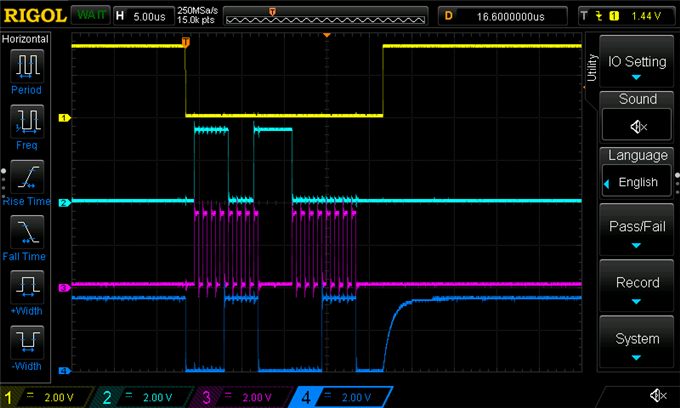
Ch.1 = CSn, Ch.2 = DI, Ch.3 = SCLK, Ch.4 = DO
SCLK speed is set at 1 MHz, which should be fine.
Does anyone have any idea what I am doing wrong here? It is almost as if the CC110L does not recognize the commands that I send.
Thanks in advance,
Best regards,
Richard

