Hi Team,
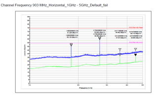
Need support to bring the 2nd and 3rd Harmonics down in the FCC Band (903 MHz ,916 MHz and 927 MHz).
Can it be controlled through registers or Keeping a 1.5 GHz LPF will be a better option....
Hi Team,
Need support to bring the 2nd and 3rd Harmonics down in the FCC Band (903 MHz ,916 MHz and 927 MHz).
Can it be controlled through registers or Keeping a 1.5 GHz LPF will be a better option....