This thread has been locked.

If you have a related question, please click the "Ask a related question" button in the top right corner. The newly created question will be automatically linked to this question.

CC1310: Reset Vectors, Bootloader, CMD, CFG and the build process

Part Number: CC1310
Other Parts Discussed in Thread: SYSBIOS,

Hello,

I have 2 designs, one will incorporate the use of the bootloader (has external EEPROM), and another design that will not need require a bootloader (No external EEPROM or UART connection). I'm trying to understand the entire bootloader process and how it works within the TI RTOS Eco-System.

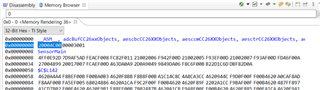
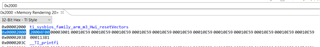
The processor exception address location starts at address 0x00000000 - 0x03C (exceptions). I see that the system creates a structure of ti_sysbios_family_arm_m3_Hwi_resetVectors which is placed at 0x2000  (see pic below) which has what appears to look like that right structure but should reside at address 0x0 instead of 0x2000 as shown below? It is setup properly as that location of 0x2000 but what I have at 0x0 is random code that is starting 0x00 which is wrong. It works fine in a debugger but doesn't run from POR when not connected to a debugger. I'm trying to find the correct configuration to:

1. bypass the bootloader for one design. (Project A)

2. Incorporate the bootloader for one design. (Project B)

3. create the proper *.CMD file to facilitate the memory map such that #1 & #2 can be created.

4. create the proper *.cfg file to facilitate the memory map such that #1 & #2 can be created.

Please note these are separate projects and will have different files that are unique to that project.

Thank you,

Shawn

  • Hi Shawn,

    If I understand you correctly you are making a bootloader based on the BIM project in the SDK?

    https://dev.ti.com/tirex/explore/node?node=APO2fo.HL5gQylkZzpGFgQ__eCfARaV__LATEST )

    This one reads the flash and checks for images with a valid header. Then jumps to the newest image. You can see the implementation of the jump in jumpToPrgEntry in bim_util.c.

    Cheers,

    Marie H.

  • Hi Marie,

    Thank you for the response.

    I'm attempting to create 2 projects, with independent requirements. Ideally I would like to have one solution that can be easily disabled (boot loader inactive) or active with a simple #define or some controlling mechanism). I'm using the TI RTOS using the CC1310_LAUNCHXL_TITROS.CMD and use an *.cfg. I've tried to look for a manual on CMD file and CFG file definitions without success. I can only learn from example only. I don't know what options are available (ie the super set of all commands). The only way I have been able to get the product to boot properly is in the debugger. It is due to having address 0x0000 (which hold the stack location) and 0x0004 (Reset vector) having other code residing at that location. When I change those locations to the values they should be by using a #pragma to force them to put values that I created via knowing the stack address and location of the Reset_ISR. I would assume (I know... I know about assuming) that the TI build process would handle this appropriately. It in fact, may work fine, if I have the proper configuration settings. 
    What I have is the .text segment being put into flash and the FLASH_BASE starts at 0x0000 (by using a CC1310_LAUNCHXL_TITROS.MCD file). What I see is actual code for some routine there, and nothing to do with the Stack location addr or Reset vector.

    I hope this further explains my issue.

  • Here is the data that is address 0x0000.

    The only way this will run without the debugger is due to the fact that I have forced a write of those values, created by me know the Stack location and Reset_ISR location for the first 8 bytes. As you can see the code base starts right after at address 0x0008 (SensorMain location). If I had not forced the write of the Stack and Reset_ISR  at address 0x0000- 0x0007, then SensorMain would have slid down to address 0x0000 which will not properly boot. 

    Here is Reset_ISR at location 0x3000:

    Here is what TI created at location 0x2000 (ti_sysbios_family_arm_m3_Hwi_resetVectors). I believe this should be at address 0x0000.

  • Hi Shawn,

    1) Here is a command file documentation:

    https://software-dl.ti.com/ccs/esd/documents/sdto_cgt_Linker-Command-File-Primer.html

    2) CFG definitions are a bit harder, I don't think we have one page listing all since this varies from device to device. We have a lot of documentation in the TI RTOS User's Guide, I'm not sure if this is what you're looking for:

    https://dev.ti.com/tirex/explore/content/simplelink_cc13x0_sdk_4_10_01_01/docs/tirtos/sysbios/docs/Bios_User_Guide.pdf

    3) It's not possible to change the reset vector location. (It's hard coded in the boot code in ROM.) So your initial image (bootloader) will need to run at this location.

    I hope this helps.

    Cheers,

    Marie 

  • Marie,

    This has help in several ways. Thank you. I have parsed the documents that you have provided and still have some questions. The bootloader is responsible for setting the vectors at 0x0000 to 0x003c? I see that the compiler puts ti_sysbios_family_arm_m3_Hwi_resetVectors at 0x2000 - 0x203C. This looks what I would expect to see at address 0x0000. As you can see my code is starting right at 0x0008, so the main exception vector are NOT being programmed appropriately. Do I need to create a Pragma setup for each of the exceptions to cause a write not only to 0x000- 0x0008 but from 0x0000 - 0x003c? Because with me right now, I only have the stack & reset vector being defined at 0x0000 - 0x0008 as a Pragma. If I have a bus fault exception for example which is defined to be at 0x0014 by the processor, that is currently having my code, so the system need to handle that appropriately which right now it is not. Ideally I want all of these fault type exception to go to one function call, and do a reboot of the system. I would like to have the this type of operation for a release build, but when debugging make that routine a simple forever loop. That I can handle within my code for the handler, but I know currently it will not work due to the vectors not being properly defined.

    How do you enable/disable the bootloader? I'm ok with having a bootloader that doesn't allow a method (USB or serial) to upload new code, so in essence making it disabled. In the other project, I wish to use a bootloader, and using one of the GPIO pins to activate the bootloader when in a particular state when POR.

    Thank you,

    Shawn

  • Hi Shawn,

    0x2000 addresses are RAM addresses (you can see this by the RAM definition in the linker command file, .cmd.)

    Then looking at the .map file, the 0x00000000 contains startup_ccs.obj (.intvecs). This again is defined in the linker cmd file:

    #if defined(KEEP_INTVECS)
        .intvecs        :  > FLASH_PAGE0_START
    #endif //KEEP_INTVECS

    You can see how all this is defined in startup_ccs.c. 

    BTW I would not recommend to change any of this, rather copy it as it is.

    You ask about disabling the bootloader. It sounds like what you would need is to disable writing anything to the device.  This can be done in the CCFG. However we don't support writing to the CCFG at runtime. 

    Could you elaborate more on the context? Are you planning to use the bootloader to program the device in production? (Did you take a look at the ROM bootloader? It's documented in the Technical Reference Manual.)

    Cheers,

    Marie H.

  • Marie,

    Once again, thank you for your help. I'll answer your questions in reverse order.

    1. The Bootloader will not be needed in production as we'll have pogo pins programming the process via JTAG. In this design there is no external EEPROM, and the code is larger than 1/2 of the code space, so a bootloader is not required. It can be in place but will not be used. In the other project, we will have an external EEPROM, and download code, which we'll use to perform and update via the bootloader. The data will get to the device by a cell module.

    2. As I debug more and more, I'm finding elements that are not making sense. I have thru my learning environment downloaded examples of various projects from TI. I am now looking back and some of those project have a tirtos_builds_cc1310_launchxl_release_ccs or equivalent project that is a dependency upon the main project example for the various examples. In other examples, I don't see that dependency. That is one aspect that make me scratch my head. What requires you to have a dependency? Can this just be a linked library that you include?

    3. I did figure out that the dependency project of 'tirtos_builds_cc1310_launchxl_release_ccs' is the sysbios (kernel portion), and the file release_pem3.c has the following section relative to our issue:

    #pragma DATA_SECTION(ti_sysbios_family_arm_m3_Hwi_resetVectors, ".resetVecs");

    /* const because it is meant to be placed in ROM */
    const UInt32 ti_sysbios_family_arm_m3_Hwi_resetVectors[] = {
    (UInt32)(&__TI_STACK_BASE),
    (UInt32)(&_c_int00),
    (UInt32)(&ti_sysbios_family_arm_m3_Hwi_excHandlerAsm__I), /* NMI */
    (UInt32)(&ti_sysbios_family_arm_m3_Hwi_excHandlerAsm__I), /* Hard Fault */
    (UInt32)(&ti_sysbios_family_arm_m3_Hwi_excHandlerAsm__I), /* Mem Fault */
    (UInt32)(&ti_sysbios_family_arm_m3_Hwi_excHandlerAsm__I), /* Bus Fault */
    (UInt32)(&ti_sysbios_family_arm_m3_Hwi_excHandlerAsm__I), /* Usage Fault */
    (UInt32)(&ti_sysbios_family_arm_m3_Hwi_excHandlerAsm__I), /* reserved */
    (UInt32)(&ti_sysbios_family_arm_m3_Hwi_excHandlerAsm__I), /* reserved */
    (UInt32)(&ti_sysbios_family_arm_m3_Hwi_excHandlerAsm__I), /* reserved */
    (UInt32)(&ti_sysbios_family_arm_m3_Hwi_excHandlerAsm__I), /* reserved */
    (UInt32)(&ti_sysbios_family_arm_m3_Hwi_excHandlerAsm__I), /* SVCall */
    (UInt32)(&ti_sysbios_family_arm_m3_Hwi_excHandlerAsm__I), /* Debug Mon */
    (UInt32)(&ti_sysbios_family_arm_m3_Hwi_excHandlerAsm__I), /* reserved */
    (UInt32)(&ti_sysbios_family_arm_m3_Hwi_pendSV__I), /* pendSV */
    };

    4. I have also found that there is a startup_ccs.c which I copied into my local project, and it has the following:

    //! The vector table. Note that the proper constructs must be placed on this to
    //! ensure that it ends up at physical address 0x0000.0000 or at the start of
    //! the program if located at a start address other than 0.
    //
    //*****************************************************************************
    #pragma DATA_SECTION(g_pfnVectors, ".intvecs")
    void (* const g_pfnVectors[])(void) =
    {
    (void (*)(void))((unsigned long)&__STACK_END),
    // 0 The initial stack pointer
    ResetISR, // 1 The reset handler
    NmiSR, // 2 The NMI handler
    FaultISR, // 3 The hard fault handler
    IntDefaultHandler, // 4 The MPU fault handler
    IntDefaultHandler, // 5 The bus fault handler
    IntDefaultHandler, // 6 The usage fault handler
    0, // 7 Reserved
    0, // 8 Reserved
    0, // 9 Reserved
    0, // 10 Reserved
    IntDefaultHandler, // 11 SVCall handler
    IntDefaultHandler, // 12 Debug monitor handler
    0, // 13 Reserved
    IntDefaultHandler, // 14 The PendSV handler
    IntDefaultHandler, // 15 The SysTick handler
    //--- External interrupts ---
    IntDefaultHandler, // 16 AON edge detect
    IntDefaultHandler, // 17 I2C
    IntDefaultHandler, // 18 RF Core Command & Packet Engine 1
    IntDefaultHandler, // 19 Reserved
    IntDefaultHandler, // 20 AON RTC
    IntDefaultHandler, // 21 UART0 Rx and Tx
    IntDefaultHandler, // 22 AUX software event 0
    IntDefaultHandler, // 23 SSI0 Rx and Tx
    IntDefaultHandler, // 24 SSI1 Rx and Tx
    IntDefaultHandler, // 25 RF Core Command & Packet Engine 0
    IntDefaultHandler, // 26 RF Core Hardware
    IntDefaultHandler, // 27 RF Core Command Acknowledge
    IntDefaultHandler, // 28 I2S
    IntDefaultHandler, // 29 AUX software event 1
    IntDefaultHandler, // 30 Watchdog timer
    IntDefaultHandler, // 31 Timer 0 subtimer A
    IntDefaultHandler, // 32 Timer 0 subtimer B
    IntDefaultHandler, // 33 Timer 1 subtimer A
    IntDefaultHandler, // 34 Timer 1 subtimer B
    IntDefaultHandler, // 35 Timer 2 subtimer A
    IntDefaultHandler, // 36 Timer 2 subtimer B
    IntDefaultHandler, // 37 Timer 3 subtimer A
    IntDefaultHandler, // 38 Timer 3 subtimer B
    IntDefaultHandler, // 39 Crypto Core Result available
    IntDefaultHandler, // 40 uDMA Software
    IntDefaultHandler, // 41 uDMA Error
    IntDefaultHandler, // 42 Flash controller
    IntDefaultHandler, // 43 Software Event 0
    IntDefaultHandler, // 44 AUX combined event
    IntDefaultHandler, // 45 AON programmable 0
    IntDefaultHandler, // 46 Dynamic Programmable interrupt
    // source (Default: PRCM)
    IntDefaultHandler, // 47 AUX Comparator A
    IntDefaultHandler, // 48 AUX ADC new sample or ADC DMA
    // done, ADC underflow, ADC overflow
    IntDefaultHandler // 49 TRNG event
    };

    5. The *.cmd that I  am using for my project has the section as follows:

    SECTIONS
    {
    .resetVecs : > FLASH_BASE
    // .intvecs : > FLASH_BASE
    // .bootVecs : > FLASH_BASE

    .text : >> FLASH
    .TI.ramfunc : {} load=FLASH, run=SRAM, table(BINIT)
    .const : >> FLASH
    .constdata : >> FLASH
    .rodata : >> FLASH
    .cinit : > FLASH
    .pinit : > FLASH
    .init_array : > FLASH
    .emb_text : >> FLASH
    .ccfg : > FLASH (HIGH)

    .data : > SRAM
    .bss : > SRAM
    .sysmem : > SRAM
    .nonretenvar : > SRAM

    /* Heap buffer used by HeapMem */
    .priheap : {
    __primary_heap_start__ = .;
    . += HEAPSIZE;
    __primary_heap_end__ = .;
    } > SRAM align 8

    .stack : > SRAM (HIGH)

    }

    It appears the .resetVecs, which as defined above, does produce what I would expect (an object 0x3C in size starting at FLASH_BASE). Which *vecs do we want to use?
    The current setup, using .resetVecs is defined in release_pem3.c and located in the dependency project. I want to use something more in-line with startup_ccs.c as it has the other error handler routines as I desire to change them to have unique handling functions (note they are currently spin functions for you to debug, but in release build (using #define) I will have them jump to the ResetISR as you don't want a bus error for example to hang up your product in real life).

    So what does this all mean? I have a better understanding but still confused as to which is proper architecture to utilize, and how to properly override when required.

    Thank you,

    Shawn

  • Hi Shawn,

    I think you may be going a bit too much into the details without getting to the code you need to make changes in.

    A simpler solution would be to add the bootloader for both of your development boards, but for the non-bootloader boards just jump directly to the application.

    (2. The tirtos builds dependency we added to minimize the build time for TI RTOS kernel. As you can see, only TI Drivers projects use this configuration. It's possible to build TI RTOS kernel in any project, as you can see in the other SDK projects.)