A related question is a question created from another question. When the related question is created, it will be automatically linked to the original question.
If you have a related question, please click the "Ask a related question" button in the top right corner. The newly created question will be automatically linked to this question.
Error connecting to the target: (Error -242 @ 0x0) A router subpath could not be accessed. The board configuration file is probably incorrect. (Emulation package 9.3.0.00032)
Re-reading your original question: The app note I sent a link to show how to use the bootlader present in ROM. What exactly are you trying to do when you get this error? (detailed description making it possible to replicate on our side)
i remove the jumpers, GND,3V3,RXD y TXD, RST and i conected 5 wires of this pins to my board. and i try to upload a example in CSS for upload the bootloader for serial by ROM
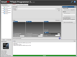
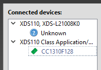
Hi, dont appear Class Aplication in FLAS PROGGRAMMER, ONLY UNKNOWN. I have my board connect to the CC1310 Launchpad. I connected GND,3V3,RXD, TXD, RST to my board whit uart
This is covered in one of the links I have sent you. That is why you have to do step 4 in the step by step description I sent you. Please follow this carefully.
Yes, but it is not clear how to do it. for example 4.1.1 SmartRF06EB Virtual COM does not make it clear that it is SMARTRF06EB, I understand that it can be replaced by FLASH PROGRAMMER 2.
Then it uses SblAppEx but it does not indicate how to run this example, do I need visual studio?
it also uses a virtual port and disconnects tx and rx and connects them down instead of up. I also have to remove VCC,GND to power my board. I mean, it's very different.
I understand that the steps for my example are:
1) connect C1310 in flash programmer
2) select
CC13xx force mass erase on the icon next to the help.
3) select program flash
and in simple select .HEX file. Then hit the play button.
4) select verify and hit play
5) press the reset button on the board
i was trying this, and upload the code in launchpad but not in my board.
Now, Im trying to use sbl program but an error occure: No response from device. Device may not be in bootloader mode. Reset device and try again. If problem persists, check connection and baud rate.
why dont detect the launchpad? i have to modify someone of code or put to low someone pin?
I suggest to first get this up and running with Flash Programmer 2 since that should be the easiest.
- Do you want to flash a launchpad with the bootloader or do you have a different HW?
- Have you verified that the chip on the board you want to flash has been erased? (Read out the flash content using the JTAG interface and Flash Programmer 2.
I have my own hardware with a CC1310F32RST. This board is externally powered and does not have a microUSB connector. I also have a CC1310 LAUNCHPAD.
1) I want to load the bootloader to my own hardware from my launchpad kit.
I have connections for uart and spi.

2) I do CC1310 force mass erase, if after this or before I do erase it gives me an error, it tells me FF address and waits for 00.
I understand that it is not done well, right?
I have loaded examples in my launchpas, but I have never loaded anything on my hardware, right now everything is just soldered and I want to load the firmware to the CC1310F32RSMT core from my launchpad
In CC1310F32RSMT the pin for default is DIO6? in code 0xFF?
Not sure what you mean here.
---
Step 1 is to see if you manage to upload an image to a launchpad using the description I have sent you earler in this thread. In that case you have to first do a mass erase first. Do you manage to upload an image using flash programmer 2?
Since your custom board has not been programmed before, you only need the 2 last steps to program it. It's not clear from previous posts what happens if you follow this description on your custom board.
IN LAUNCHPAD WORK, when i want to connect my hardware to launchpad, if remove TXD and RXD FOR CONNECT UART to my hardware. I open flas programmer 2, connect whit launchpad , force erase mass, STEP 3) select comunication port CC1310F32 and conect when i click in connect the flash programer 2 is closed.
Try removing all jumpers. Now you try to both connect to the chip on the Launchpad via the JTAG interface and then the chip on the customer board via UART.
For the customer board, only do step step 3 and 4.
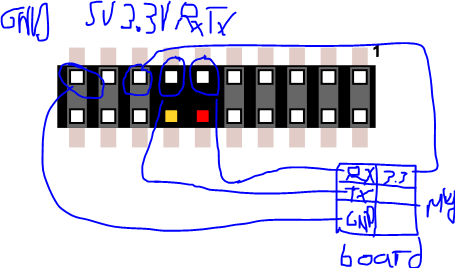
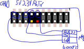
Also, could you show to which pins you are connecting RxD and TxD on your customer board.
I dont understand, i remove all jumpers less JTAG in launchpad and the i connect custom board to uart? or what do you say? if remove JTAG jumper inlaunchpad dont detect the device the flash programmer.
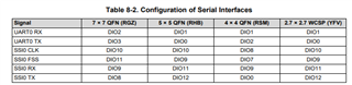
OK, the custom board is CC1310F32RSMT whit uart RX in pin DIO2, and TX in DIO1.
and i connec the wires like this
Also i try to connect in pin yellow and red but it the same.
From the beginning step by step:

1) Can you load the bootloader from a CC1310F128 to a CC1310F32?

2) If the answer to the first question is yes.
the next step is to establish how it is done.
is sblAppEx used or can flash programmer be used?

3) determine the connection of the two plates.
-For sbl I understand that it is as indicated in the figure of the link jumpers.
-For flash: can you indicate the connections and jumpers?

4) if the response is flash, then:
- Flash opens.
-I select XDS110 Class Application/User UART (COM10) and the CC1310F32
- connect.
-load .hex
-select program.
-Click on the play button and that's it.
If the answer is sbl:
-run sbl.
In this part I don't know how to load the program.
Not sure what you mean. What you have tried so far is to use the UART available via the XDS110 debugger (virtual COM port).
2)
As already covered, you can do this with flash programmer 2 and Uniflash. Probably also SblAppEx but it looks like a GUI is easier at this stage. For production you can use the CLI provided for Flash Programmer 2 and Uniflash
3) For both programs the same connection should be used.
VDD, GND; nReset, TxD, RxD.
ALL jumpers have to be removed when using the XDS110 on a Launchpad for this. You want to connect to ONLY the DUT and not t he CC1310 on the Launchpad.
4)
Note step (3) and (4) in my how to do list. Since using UART will not autodetect the CC1310 you have to select this manually from the pull down. After you have manually selected the chip, you can right-click and select connect.
Note step (3) and (4) in my how to do list. Since using UART will not autodetect the CC1310 you have to select this manually from the pull down. After you have manually selected the chip, you can right-click and select connect.
In your image for the list, you select comunication port but should be XDS110 Class Application not?
after select connect, what i should do? select program and play? or erase..program and verify?
I have tried to connect it as you said. all jumpers removed, VCC. GND, nRST, RX,TX.
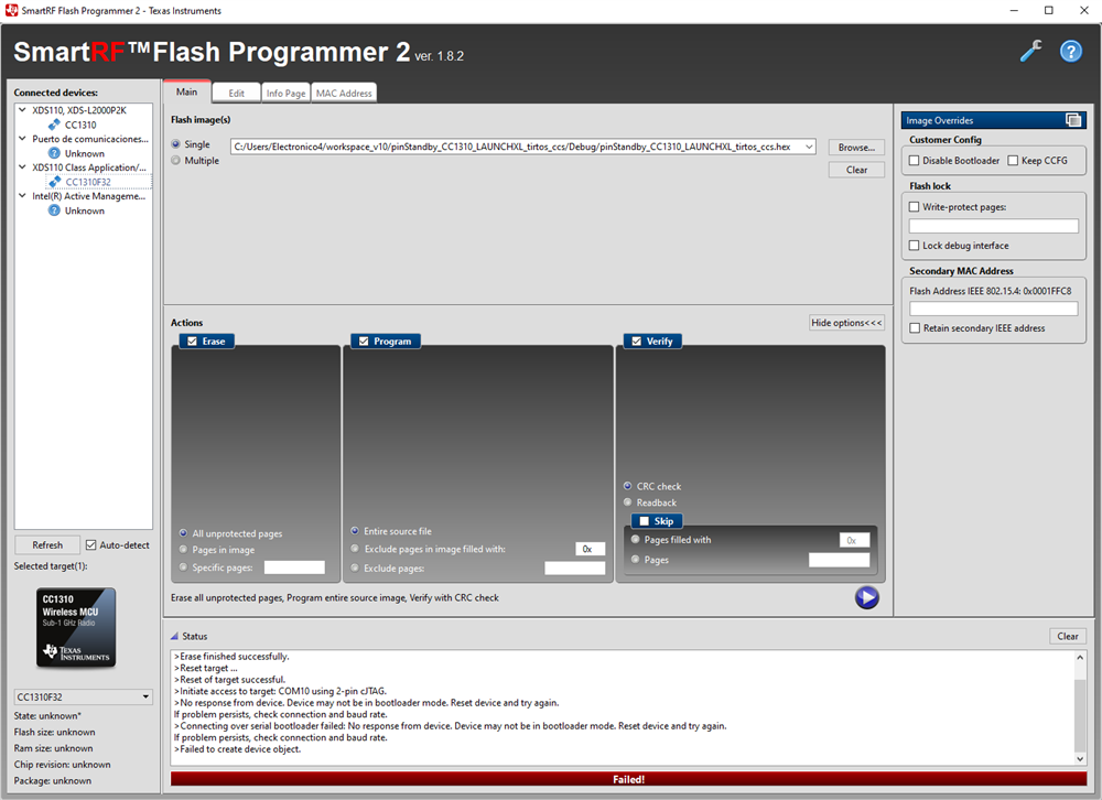
When using FLASH programmer, I get this error when trying to connect.
>Initiate access to target: COM10 using 2-pin cJTAG.
>No response from device. Device may not be in bootloader mode. Reset device and try again.
If problem persists, check connection and baud rate.
>Connecting over serial bootloader failed: No response from device. Device may not be in bootloader mode. Reset device and try again.
If problem persists, check connection and baud rate.
i have try to use 2 launchpad for connect and dont connect it. its a error or if you want to use flash programmer you need have 2 jumpers connected in TMS andTCK?