This thread has been locked.

If you have a related question, please click the "Ask a related question" button in the top right corner. The newly created question will be automatically linked to this question.

CC-ANTENNA-DK2: How to determine the matching for the desired frequency in the CC-Antenna-DK2 antennas?

Part Number: CC-ANTENNA-DK2

Hi all,

I have the CC-Antenna-DK2, and a few launchpads. Both the "quick start guide" and the "antenna measurement summary" documents refer that some antennas can be configured for either 868 or 915MHz, however those whose bandwidth is not  enough to work on both frequencies, require a single match adjusted for the final desired frequency. 

Some antennas do provide 2 tables with the individual components values, for different possible frequency matches. For example on "CC-Antenna-DK2 and Antenna Measurements Summary (Rev. A)", antenna #1 has a table with the matching components for single band 2.4GHz (section 2.1.1.1 table 4) and a table for dual band 868 and 2.4GHz (section 2.1.1.2 table 5). But even though this antenna is also capable of working on 915MHz, it has no information on what the matching values would be for 915MHz. All it says is "Can also be tuned for 915/920 MHz and 2.4 GHz with a new matching network."

My question is how do I know what values I need for each component in the antenna matching section for the frequencies I want in each antenna of the kit? I cannot find any indication on the documentation on how this values can be obtained.

Thank you
  • Hi,

    There is a new antenna application note that describes how to match antennas in more detail: https://www.ti.com/lit/swra730

    Regards,

       Richard

  • Hi Richard, 

    Thanks for the information, I didn't know about the existence of that application note. It definitely helps to shed some light into this matter but it still doesn't completely clear my question.

    Even though I now have a greater understand thanks to the application note you sent me, there are still many cases where the calculations and BOM values used make no sense to me.

    I can give one example using that new application note (there are several others on the CC-Antenna-DK2 measurements summary document). Please try to follow my reasoning and try to help me understand what am I doing wrong here.

    Lets take as an example the single match for 510MHz on this new app note (swra730):

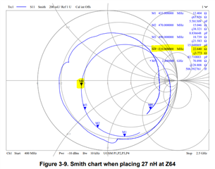
    1 - Figure 3-9 (page 12) shows unmatched impedance for frequency sweep with 27nH at Z4 (calibration for 510MHz), marker M4 (510MHz) has impedance of 22.640 - 3.773j.

    2 - Table 4-4 (page 24) shows BOM for single band 510MHz operation.  


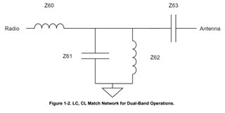
    3 - Figure 1-2 (page 5) shows schematic for matching network.

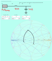
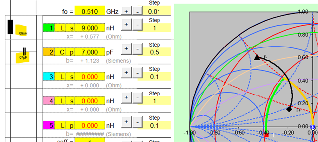
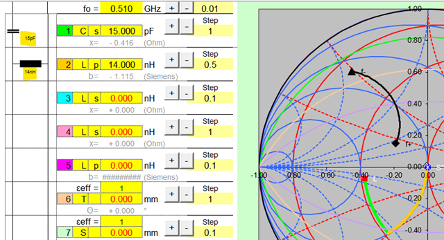
    4 - So according to schematic of matching network and BOM, we only have Z63 which is actually an inductor and Z62 which is actually a capacitor. Using a smith chart tool with your BOM values we get this for 510MHz at 50R characteristic impedance: 

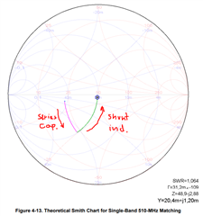
    5 - Figure 4-13 (page 24) shows TI's theoretical match for 510MHz. However in here you seem to use a series capacitor for Z63 and a shut inductor for Z62:


    So why does the theoretical and actual BOM smith charts look so different? Why was Z63 switched from series capacitor to series inductor, and Z62 from parallel inductor to parallel capacitor? I know the final BOM has further tuning, but this completely reverses the components used. The theoretical components make sense, figure 4-13 makes sense according to antenna matching theory and according to figure 1-2, but the actual BOM components are switched, why? What am I missing here? 

    Thank you

  • For the antenna match it is not known in the beginning if it is an inductor or a capacitor that is required; that's why we give the components a general impedance reference "Z". It is common that the values from the theoretical components and real components usually deviate slightly in the Smith chart. The theoretical components are a pure inductance or capacitance. Whereas real components are a mixture of RLC.

    The antenna can be matched in a high-pass or low-pass manner; both are correct.

    For example:

    or

    Regards,

       Richard

  • Thanks Richard,

    So basically I need a VNA to get actual impedance and Return Loss measurements, and then have to play with the theoretical and actual real values back and forth until I get the desired match?

  • The final values of the antenna match should always be confirmed with a VNA measurement. 

  • Ok thanks Richard