This thread has been locked.

If you have a related question, please click the "Ask a related question" button in the top right corner. The newly created question will be automatically linked to this question.

CC1200: transmitting signal spectrum lobes

Part Number: CC1200

Hello,

I have problem with CC1200 test mode. When I configure transceiver for continual transmitting unmodulated signal (the same with modulated) I get signal spectrum like this.

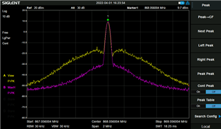
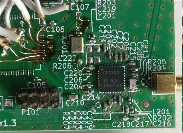
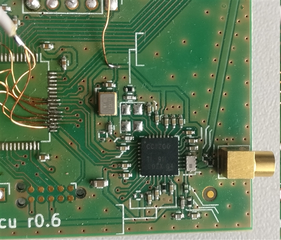
where the purple spectrum is from CC1200 wired to TI CC debugger and the yellow one is  when CC1200 is configured via our MCU. In both cases I use the same PCB where once is CC debugger connected and once is MCU placed.  The main problem I am facing now are lobes around carrier frequency, I don't know why they appear here at all.  If anyone have any idea please let me know.

Configuration generated from RFStudio is here

static const registerSetting_t preferredSettings[]=
{
  {CC1200_IOCFG2,            0x08},
  {CC1200_SYNC3,             0x6F},
  {CC1200_SYNC2,             0x4E},
  {CC1200_SYNC1,             0x90},
  {CC1200_SYNC0,             0x4E},
  {CC1200_SYNC_CFG1,         0xE8},
  {CC1200_SYNC_CFG0,         0x23},
  {CC1200_DEVIATION_M,       0x47},
  {CC1200_MODCFG_DEV_E,      0x0B},
  {CC1200_DCFILT_CFG,        0x56},
  {CC1200_PREAMBLE_CFG1,     0x00},
  {CC1200_PREAMBLE_CFG0,     0xBA},
  {CC1200_IQIC,              0xC8},
  {CC1200_CHAN_BW,           0x84},
  {CC1200_MDMCFG0,           0x05},
  {CC1200_SYMBOL_RATE2,      0x94},
  {CC1200_SYMBOL_RATE1,      0x7A},
  {CC1200_SYMBOL_RATE0,      0xE1},
  {CC1200_AGC_REF,           0x27},
  {CC1200_AGC_CS_THR,        0xF1},
  {CC1200_AGC_CFG1,          0x11},
  {CC1200_AGC_CFG0,          0x90},
  {CC1200_FIFO_CFG,          0x00},
  {CC1200_FS_CFG,            0x12},
  {CC1200_PKT_CFG2,          0x06},
  {CC1200_PKT_CFG0,          0x40},
  {CC1200_PA_CFG1,           0x36},
  {CC1200_PKT_LEN,           0xFF},
  {CC1200_IF_MIX_CFG,        0x18},
  {CC1200_TOC_CFG,           0x03},
  {CC1200_MDMCFG2,           0x03},
  {CC1200_FREQ2,             0x56},
  {CC1200_FREQ1,             0xCC},
  {CC1200_FREQ0,             0xCC},
  {CC1200_IF_ADC1,           0xEE},
  {CC1200_IF_ADC0,           0x10},
  {CC1200_FS_DIG1,           0x04},
  {CC1200_FS_DIG0,           0x50},
  {CC1200_FS_CAL1,           0x40},
  {CC1200_FS_CAL0,           0x0E},
  {CC1200_FS_DIVTWO,         0x03},
  {CC1200_FS_DSM0,           0x33},
  {CC1200_FS_DVC1,           0xF7},
  {CC1200_FS_DVC0,           0x0F},
  {CC1200_FS_PFD,            0x00},
  {CC1200_FS_PRE,            0x6E},
  {CC1200_FS_REG_DIV_CML,    0x1C},
  {CC1200_FS_SPARE,          0xAC},
  {CC1200_FS_VCO0,           0xB5},
  {CC1200_IFAMP,             0x05},
  {CC1200_XOSC5,             0x0E},
  {CC1200_XOSC1,             0x03},
  {CC1200_PARTNUMBER,        0x20},
  {CC1200_PARTVERSION,       0x11},
  {CC1200_MODEM_STATUS1,     0x10},
  {CC1200_XOSC_TEST1,        0x00},
};

Lukas

  • From the two plots it looks like they are done with different phase noise settings. I assume that you have double checked that for both plots the exact same register settings are used? 

    If that is the case, are you powering the CC1200 through the CCDebugger?  If so, could you try to power it through a lab supply, it could be that the USB power in the CCDebugger has some noise that impact the results. 

  • Hello,

    the settings of spectrum analyzer is the same for both measurements. The purple plot is from PCB without MCU and connected to CC debugger. After hours of testing I realized that I have two PCB versions which differs just by MCU version and few wires. So I removed MCU from both of them and I connected CC1200 directly to CC debugger. As result I can see now that output signal is not depending on MCU and its code for sure. One PCB transmit still yellow plot signal with lobes. Now I suppose that here is HW problem somewhere but how to find it. PCB part with transceiver was not changed at all and I don't have a clue what could cause such bad signal shape.

    In the left picture there is version with yellow signal in the right picture is version with purple signal. There are no significant changes in the layout, all what I wanted to achieve was change MCU for more powerful version stm32f413 instead of f401. You can see wiring for CC debugger so MCU is not here now.  Any ideas?

    Thanks

  • From the two plots it looks like they are done with different phase noise settings. I assume that you have double checked that for both plots the exact same register settings are used?

    Not sure if this was answered. I'm referring to the register setting and not the spectrum analyzer settings. 

    But to see if I understand the new information correctly:

    You have two slightly different versions of the PCB. The MCU is running the same code and use the same register settings on both boards. And when the MCU is controlling the CC1200 (or the CCDebugger) you get different phase noise for the two different boards? If my understanding is correct, what exactly are the differences between the two boards? 

  • You are right, is is exactly like you said. Main difference between two PCB version is that on new version MCU has external HP crystal installed. I believe there is no way that this could affect CC1200 especially when I removed MCU on both board and used CC debugger and  spectrum is the same.  I am not sure what can cause such spectrum change. CC1200 looks very stable, touching around with probe has no effect on spectrum. I could send you PCB layout and schematic if it would be helpful.

  • You can use https://www.ti.com/tool/SIMPLELINK-SUB1GHZ-DESIGN-REVIEWS to request a review, I will pick up the request. 

    Have you changed something with regards to the power/ decoupling on the CC1200 side? 

  • No I have not. PCB around CC1200 is untouched.

  • Does the MCU only set up the registers, strobe TX and then go to sleep or does  the MCU has some other activity? 

  • It doesn't matter if MCU does or doesn't anything.  MCU configure registers for continual transmission unmodulated signal. When I am debugging MCU and MCU is stopped this is not affecting spectrum. I have removed MCU from both boards and connected CC debugger directly. This has no effect on spectrum. Now when I use CC debugger and RF studio with the same settings one PCB has bad spectrum other has not. It is weird.