Other Parts Discussed in Thread: WMBUS, , CC1312R7, CC1101, CC1200
Hi,
I have successfully performed rx measurements on Wmbus OTM sending packets either between 2 boards or between an ESG 4438C signal generator and a LP-CC1312R7 evaluation board in rx mode.
This worked using the setup "50kbps , 25 kHz deviation, 2GFSK, 100kHz deviation"
OTM tx, working ok
OTM rx, working ok
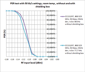
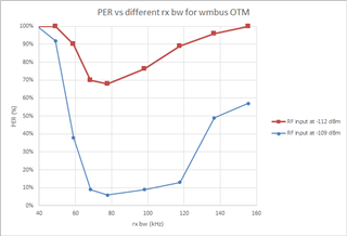
Rx PER for wmbus OTM for different rx bw settings
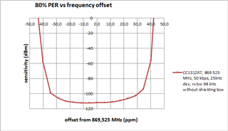
PER vs tx frequency offset
Impact of frequency offset on PER for wmbus OTM , looks similar to figure 7-16 in the CC1312R7 datasheet.
I think the text is wrong for figure 7-16 in the DS for CC1312R7 as it is the same text for figure 7-15 too.
The receiver for Wmbus OTM rx settings can meet class 1.5 requirement for EN 300220.
I now would like to do the same on Wmbus MTO using the same sync word, payload, crc i.e. f carrier 868.95 MHz, 100kbps, 45kHz deviation,
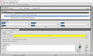
To do so i use the typical settings "WMBUS C-mode 100kbps , 2(g)fsk 235kHz rx bw, presilicon settings where i update the settings as following
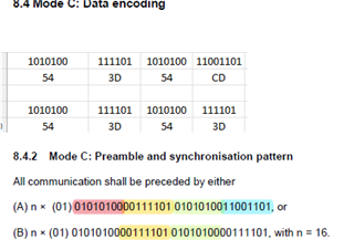
- sync word : 543D543D (wmbus frame B)
- payload :756B7F56
- crc : 80DE
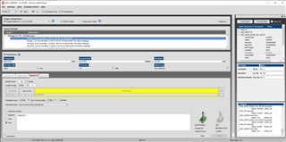
MTO tx settings
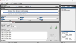
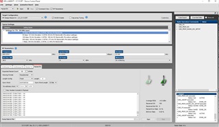
MTO rx settings, not OK
There is a 1 byte offset for the received data which will therefore be considered as faulty.
I get the same results when using a signal coming from the transmitter from a second LP-CC1312R7 or from the ESG4438C
Is there a work around or another