This thread has been locked.

If you have a related question, please click the "Ask a related question" button in the top right corner. The newly created question will be automatically linked to this question.

CC1120: Questions on registers of part number

Part Number: CC1120
Other Parts Discussed in Thread: CC1125,

Hi team ,

One of my customer is migrating from CC1125 to CC1120 and they are now reading the part number to distinguish from these two parts.

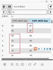
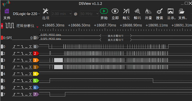
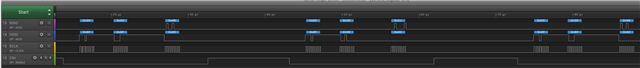
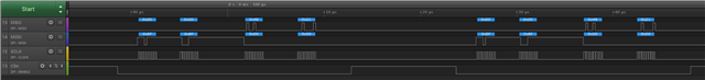
But when they read the register of part number, the value sometimes reads to be 0x00 which should be 0x48.

Could u help to explain the possible reason and provide some other ways to distinguish these two parts?

  • Hi team ,

    One more thing to add is that the register of part version is right.

    And because the customer is working from home and they disable to test the plot of SPI lines right now. Could u provide some suggestions to help them check the problem?

  • The only way (from a software perspective) to distinguish between these parts is to read the part number. 

    Also, if they read out an unexpected value, this indicate that the SPI is not correctly setup. Do they have any chance getting hold of a logic analyzer or a oscilloscope to check the SPI interface (I assume that this is difficult from a practical standpoint)

    Is this the only register they have problem reading? If they reset the chip and read back the values of the various registers they should read the reset values. Is that the case? 

    Have they seen an issues working with CC1125 before? From a SPI interface perspective the two parts are equal meaning that if they have code running with CC1125 this should also running with CC1120. The only difference could be timing if they have used 40 MHz xtal on CC1125 since CC1120 uses 32 MHz xtal.   

  • Hi Ter,

    Thanks for your quick response!

    This is the only register they have problems reading and the crystal they set is 32MHz.

    They have found the same problems in CC1125 and have u heard about the same problem before?

    Do u have advice about distinguishing these two products except reading the part number?

  • We have never heard of this before, and there are no other way to distinguish between the parts. 

    Have they monitored their SPI bus using a scope to see if this is according to speck?

    Can you please provide a plot of the SPI communication (all 4 lines) to show that the read from this register is 0 ?

    Siri

  • Hi Siri,

    I have pass your answer to the customer.

    And one more question is that is there any possibility of the register being overwritten by other write registers because Busrt successive writes ?

  • The PARTNUMBER register is read only, and cannot be overwritten.

    Siri

  • Hi Siri,

    They have used the logic analyzer to watch the SPI plots as attached.

    The logic they read the register is as following:

    1. Reading the four registers starting from partnumber register address by busrt;

    2.The first instruction of boot up reads four registers starting from partnumber in succession, partbnumber and partver are OK, and the screenshot of the packet captured by the logic analyzer is as follows.

    3. After that, go on reading the four registers starting from partnumber. Partnumber value is 0x00 (not normal), partver is OK, the logic analyzer to catch the packet screenshot is as follows.

    We summarize the law:
    1, read this partnumber ID register must ensure that it is the first instruction of the operation cc112x, as long as it is put behind, it will fail, it is very strange.
    2, to lengthen the interval with the instruction behind, the interval is low in time is the first instruction is also prone to failure, we are now to ensure that the operation of the degree partnumber and the instruction behind the interval of more than 2S;.

    CC1125 is also the same.

    Could u kindly help to explain the case?

  • Hi Zoey

    There is so much going on in the plots you sent me in the .dsl file, so I would appreciate if you could simplify the test, and also just send a plot of the 4 SPI lines (and not everything else that I do not know what is):

    Also make it clear in the plots you are sending which line is SCLK, CSn etc.

    I did a quick test on a CC1120, and the only thing the code is doing is reading two registers in a loop:

    void main(void) {
    
        // Initialize MCU and peripherals
        initMCU();
        
        trxSpiCmdStrobe(CC112X_SRES);
    
        while(1) {
            cc112xSpiReadReg(CC112X_PARTNUMBER, &dummy, 1);
            cc112xSpiReadReg(CC112X_PARTVERSION, &dummy, 1);
        }
    }

    I am repeatedly reading 0x48 from the PARTNUM register and 0x21 from the PARTVERSION register.

    this looks like this one the logic analyzer:

    If I do a burst read instead:

    void main(void) {
    
        // Initialize MCU and peripherals
        initMCU();
        
        trxSpiCmdStrobe(CC112X_SRES);
        
        while(1) {
            cc112xSpiReadReg(CC112X_PARTNUMBER, &dummy[0], 2);
        }
    }

    It looks like this:

    Please provide similar plots.

    Also make sure that you start by resetting the device (SRES).

    Siri