This thread has been locked.

If you have a related question, please click the "Ask a related question" button in the top right corner. The newly created question will be automatically linked to this question.

CC1120: CC1120 - SO delay on CS for some parts

Part Number: CC1120


So, I've built quite a few 'CC1120 RF boards', which are an exact copy of the TI recommended design with 434MHZ.  I connect them up to both RX and TX boards that we designed.  They work quite well and are quite reliable.  On occasion, (I've had 3) I've had boards that stopped working shortly after they transmit packets.  Reset the RF chip and it transmits for a few packets and stops. Unless the chip is reset, SO never goes low after CS again.

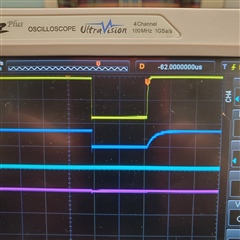
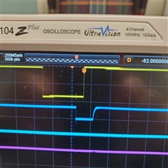
After investigation, all 3 have the same phenomenon.  Before it stops, when CS goes low, SO does not follow for 30ms or so.  All other boards (working boards), SO follows CS almost, if not immediately.  The RF board follows the problem.  So, I know its the board.  I don't know if a part is wrong, but everything looks OK.  I could toss the 3 boards in the trash and move on, but thought someone might have something to look at before I do that.  It's odd that 3 boards (out of ~100) have the same issue.  So, it's mostly like the same issue.  Any ideas?

  • The first bit in the status byte returned on the MISO line is the CHIP_RDYn signal. If this is not pulled low when CSn is pulled low, this indicates that the crystal is not stable.

    Siri

  •  

    Yeah.  We tried changing the crystal and no change.  The left is all the good RF boards.  SO (blue) follows CS (yellow).  The right is one of the bad ones, as SO lags way behind CS.

  • If you take one of bad board and one good board and swap the cc1120's. Does the problem follow the board or the device?

    This is obviously not a SW issue, so I will hand this case over to a colleague of mine, working with HW.

    BR

    Siri

  • Changing the chip solved the problem using the same board.  The waveform is now perfect and all packets send great.  So, there is something that happens sometimes that causes the CS-SO to be lagging.  In this case, the chip still commands fine, but packets are not sent out reliably.  I thought it may be a wrong part on our RF board, but it appears to be a chip issue.

  • Can you also test on a bad board to re-solder the same CC1120. i.e. do not swap but just to lift and re-solder the same chip to see if this is an issue with soldering ?

    If you have access to x-ray equipment, to examine the soldering on the GND pad of the QFN of a good unit and a bad unit. 

  • We really don't have the ability to do that - put a part that small down twice.  We don't have a reflow oven, just a hot air gun.  These parts, often times become unusable or damaged when we remove them for another part.  We could try, but I think if it doesn't work at all, then we won't know whether we damaged the part or it was still suspect.  Also, upon more monitoring, the new CC1120 chip we put down seems to miss a lot of packets from time to time making me think there is a part wrong on the RF board.  I guess one of the inductors could be wrong.  Not sure.

  • CC1120 is quite robust and a hot-air gun should be sufficient for re-soldering providing that the maximum temperature is controlled. We normally just use a hot-air soldering iron and a soldering plate to re-solder the QFNs in the lab. The soldering plate is normally set about 50 degrees under the soldering melting point and we just heat locally with an hot-air soldering iron to melt the solder for the component to be replaced.

    If you have swapped the CC1120 and the board works then it could of been the CC1120 or poor soldering that caused the issue. 

    Can you share your schematics ?

    If there has been a mistake in the production with an incorrect part, then this should be seen on all the boards that were produced at that particular time. Visually compare a good board and a poor board on all of the CC1120 passive components so that the parts have the same coloring, marking etc. to try to find out if an incorrect part has been used by mistake.

  • 160-4020A2.pdf

    See our RF board schematic.  It has been seen before when we had previous questions.  Should be an exact copy of the TI test board.  All signals are fed on connectors to either our RX or TX boards.  Visually, even if you have incorrect part, part colors on small surface mounts are normally the same, so it's hard to determine if part is wrong value or not.

  • Agree that the schematic looks fine. If you receive additional information that can help debug, please post otherwise it is difficult to conclude other than this can be related to soldering or perhaps incorrect assembly at production.