This thread has been locked.

If you have a related question, please click the "Ask a related question" button in the top right corner. The newly created question will be automatically linked to this question.

LP-CC1312R7: Build interface to run RF test in python

Part Number: LP-CC1312R7
Other Parts Discussed in Thread: CC1312R7

Hi there,

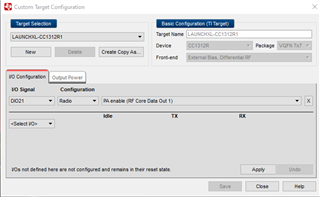
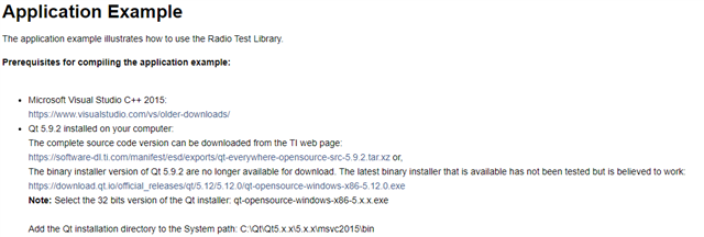
I'm trying to build a python library interface to access all features provided in TI's radio_test_lib_app for LP-CC1312R7, The main reason is that we want to have an automated method to run the RF tests and get the result logged, also because the other equipment we use have python library support. I did a search online and found method to wrap C++ library into python libraries. But I'm curious that if you have a better approach to generate the libraries directly for python.

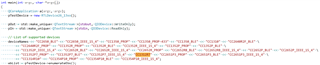
On the other hand, we are also trying to generate the c++ radio_test_lib_app that supports CC1312R7 to start RF test without SmartRF Studio to get a better understand about commands being transmitted over UART. In the linked ticket you mentioned that the sample code needs updates to enable CC1312R7 support. Would you point me to the instructions as well? I'm using MinGW g++ compiler under windows 11 OS.

Thanks a lot for the help,

Yuelin 

  • Hi there, 

    Additional question about custom target configuration tools. The access to config GPIO and radio power seems to be available in SmartRF Studio 7 only, i.e, there's no menu for those config in the radio_test_lib_app command line app. Is there a way to enable GPIO and radio power configuration in the command line app as well?

    Thanks,

    Yuelin

  • Hi Yuelin,

    Unfortunately, we do not provide any examples or similar for using the Radio Test Library (RTLib) with python and we have any suggestions for you , but it is probably possible. Keep in mind that RTLib is using the Qt library. 

    For your information, the RTLib (and SmartRF Studio) does not communicate with the device using UART, it is using the JTAG debugger to interact with device.  


    These are the steps you need to perform to enable support for CC1352R7 in the radio_test_lib_app example:
    Add CC1312R7 to list of devices (deviceNames) in the main function:

    Add entry for CC1312R7 to getCategoryAndSetting:

    void getCategoryAndSetting(const QString& devId, QString& category, QString& setting)
    {
        if (deviceName == "CC2650_BLE")
        {
            category = "Settings";
            setting = "setting_ble_1mbps.xml";
        }
        ...
        else if (deviceName == "CC1312R7")
        {
            category = "Settings for 779 - 930 MHz band";
            setting = "setting_tc106.xml";
        }
    }

    Add entry for CC1312R7 to getTargetName:

    void getTargetName(const QString& devId, QString& targetName)
    {
        if (deviceName == "CC2650_BLE")
        {
            targetName = "CC2650EM-7ID";
        }
        ...
        else if (deviceName == "CC1312R7")
        {
            targetName = "LP_CC1312R7";
        }
    }


    I am not sure exactly what you are asking for regarding the GPIO and power configuration, but you can control the TX power by doing something similar to what is done in setMaxOutputPower (setting the "txPower" parameter).

    Regards,
    Nikolaj

  • Hi Nikolaj,

    Thank for your reply. By configing GPIO I was wondering if RTLib has the similar feature as "Custom Target Configuration" in Smart RF studio to access the GPIOs as following


    so I can connect to CC1352R7 and toggling the GPIOs from command line.

    Thanks,

    Yuelin

  • Hi Nikolaj,

    I also have a question about how to open the project. I have MS visual studio 2022 installed, but I don't find a .vcxproj file under \ide\windows\msvc2015\radio_test_lib_app_ex. Also VS2022 can not find a project file within the entire folder that I installed directly from Smart RF Studio 7-> Tools -> SmartRF Test Environment -> SimpleLink Wireless MCUs(CC26xx and CC13xx). Is there anything I missed during the installation? Can you point me to the proper tool chain that I can use to update the source code and compile the executable that has CC1312 support?

    Thanks a lot for your help,

    Yuelin

  • Hi Yuelin,

    I will get back to you regarding the GPIO configuration.

    Visual studio projects are generated using QMake.
    To generate the projects you need to execute \ide\windows\msvc2015\radio_test_lib_app_ex\qmake_app_ex.bat.

    You might be able to use MS visual studio 2022, but we have only tested it using MS visual studio 2015. Please refer to the Prerequisites segment in the documentation: https://software-dl.ti.com/lprf/smartrftm_studio/docs/rtlib/html/index.html

    By the way, have you considered using the rfDiagnostics example to achieve your goal? Refer to https://dev.ti.com/tirex/explore/node?node=AC9ve61.sPHFX4r3P3UaDQ__BSEc4rl__LATEST. This provides an AT API to be used with UART, which might be easier for you to integrate with Python.

    Regards,
    Nikolaj

  • Hi Nikolaj,

    Is there any update on enabling GPIO configuration on sample app?

    Using AT API looks like an interesting idea. I didn't have a chance to install the Simple Link SDK. But at first glance on the command supported on both RFLib and rfDiagnostics I want to confirm whether "Frequency offset" command in RFLib is also available on rfDiagnostics, or is there anything we need to develop to work with rfDiagnostics to have that feature. Writing an AT command parser on python would be easier than wrapping C++ libraries in my opinion.   

    Thanks,

    Yuelin

  • Hi Yuelin,

    The out-of-the-box rfDiagnostics example does support retrieving the frequency offset, but you could probably easily add the functionality by modifying the example.

    To answer you question regarding using a custom target configuration in RTLib. This is what you need to do:

    1. Generate the the target configuration using SmartRF Studio 7 (let's assume you called it 
      copy_CC1312R7)
    2. Copy the generated target xml file to config\xml\cc1312r7\targets in the RTLib installation directory
      1. I believe the default location of the SmartRF Studio generated file is at C:\Users\xxxxxxxx\Documents\Texas Instruments\SmartRF Studio v7\config\xml\cc13xx_cc26xx\targets\target_copy_CC1312R7.xml
    3. Add a element for the new target configuration to config\xml\cc1312r7\targets\targets.xml
      1.  <VirtualTarget name="copy_CC1312R7">
            <Target>target_copy_CC1312R7.xml</Target>
          </VirtualTarget>
    4. Add the RfDesign element from the SmartRF Studio generated pasettings file to config\xml\cc1312r7\targets\pasettings.xml 
      1. I believe the default location of the SmartRF Studio generated file is at C:\Users\xxxxxxxx\Documents\Texas Instruments\SmartRF Studio v7\config\xml\cc13xx_cc26xx\targets\pasettings_copy_CC1312R7.xml
    5. Modify config\xml\cc1312r7\targets\target_copy_CC1312R7.xml to point to pasettings.xml instead of pasettings_copy_CC1312R7.xml

    Regards,
    Nikolaj