This thread has been locked.

If you have a related question, please click the "Ask a related question" button in the top right corner. The newly created question will be automatically linked to this question.

CC1310: Code only running in debug

Part Number: CC1310

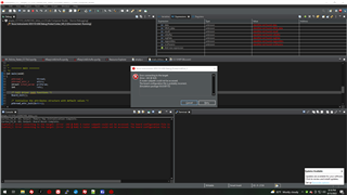
I have develop a custom board with the CC1310F128RGZ and CC1312 as the debugger and programmer. I am using the "empty" project to do some initial tests, but I am experiencing a problem where the code only seems to run while in debug mode and manually stepping (F6) though the code with breakpoints. If i remove the breakpoints and continue even in debug, the code does not run. The code does not seem to run even when exiting out of debugging.
I have set LF XTAL to #define SET_CCFG_MODE_CONF_SCLK_LF_OPTION 0x3// LF RCOSC and this does not seem to fix the issues. 

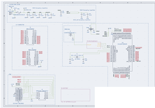
Also my custom board is built referencing the C1310 LP Schematic and PCB Design Guidelines. Below is an image of the schematic of the custom board

  • Hi Corey,

    Can you please explain your setup in more detail? When you say that you use "CC1312 as the debugger and programmer", are you referring to the XDS110 on a CC1312 launchpad (https://www.ti.com/tool/LAUNCHXL-CC1312R1)?

    Can you also explain what you observe when you say the code is not running? If you resume the CPU and later halt it, will it be halted at the same place as where you resumed it from?

    Thanks,
    Nikolaj

  • Yes, I apologize for the lack of detail. I am using the XDS110 on a CC1312 launchpad (disconnecting all the jumpers P4)  and using the JTAG 

    So my example code I am having DIO_24 toggle ON and off which causes an LED to blink. I have performed some additional testing and changed some settings (changed CCS Target Config JTAG/SDW/cJTAG Mode from 2pin to 4-pin standard) and now code will run (Blink LED), while debugging and NOW also will run (blink LED) if i simply load the program. But if I remove power and reapply power to the target board the code does not run (Blink LED). So it seem like I am getting better results but the code does not seem to run (Blink LED) after power cycle. Below is the code . I also included the ccfg.c file that is being referenced (default) 

    example code

    /*
     * Copyright (c) 2015-2019, Texas Instruments Incorporated
     * All rights reserved.
     *
     * Redistribution and use in source and binary forms, with or without
     * modification, are permitted provided that the following conditions
     * are met:
     *
     * *  Redistributions of source code must retain the above copyright
     *    notice, this list of conditions and the following disclaimer.
     *
     * *  Redistributions in binary form must reproduce the above copyright
     *    notice, this list of conditions and the following disclaimer in the
     *    documentation and/or other materials provided with the distribution.
     *
     * *  Neither the name of Texas Instruments Incorporated nor the names of
     *    its contributors may be used to endorse or promote products derived
     *    from this software without specific prior written permission.
     *
     * THIS SOFTWARE IS PROVIDED BY THE COPYRIGHT HOLDERS AND CONTRIBUTORS "AS IS"
     * AND ANY EXPRESS OR IMPLIED WARRANTIES, INCLUDING, BUT NOT LIMITED TO,
     * THE IMPLIED WARRANTIES OF MERCHANTABILITY AND FITNESS FOR A PARTICULAR
     * PURPOSE ARE DISCLAIMED. IN NO EVENT SHALL THE COPYRIGHT OWNER OR
     * CONTRIBUTORS BE LIABLE FOR ANY DIRECT, INDIRECT, INCIDENTAL, SPECIAL,
     * EXEMPLARY, OR CONSEQUENTIAL DAMAGES (INCLUDING, BUT NOT LIMITED TO,
     * PROCUREMENT OF SUBSTITUTE GOODS OR SERVICES; LOSS OF USE, DATA, OR PROFITS;
     * OR BUSINESS INTERRUPTION) HOWEVER CAUSED AND ON ANY THEORY OF LIABILITY,
     * WHETHER IN CONTRACT, STRICT LIABILITY, OR TORT (INCLUDING NEGLIGENCE OR
     * OTHERWISE) ARISING IN ANY WAY OUT OF THE USE OF THIS SOFTWARE,
     * EVEN IF ADVISED OF THE POSSIBILITY OF SUCH DAMAGE.
     */
    
    /*
     *  ======== empty.c ========
     */
    
    /* For usleep() */
    #include <unistd.h>
    #include <stdint.h>
    #include <stddef.h>
    
    /* Driver Header files */
    #include <ti/drivers/GPIO.h>
    // #include <ti/drivers/I2C.h>
    // #include <ti/drivers/SPI.h>
    // #include <ti/drivers/UART.h>
    // #include <ti/drivers/Watchdog.h>
    
    /* Board Header file */
    #include "Board.h"
    #include <ti/drivers/PIN.h>
    
    /* Pin driver handles */
    
    static PIN_Handle ledPinHandle;
    
    /* Global memory storage for a PIN_Config table */
    static PIN_State buttonPinState;
    static PIN_State ledPinState;
    
    #define RLED IOID_24
    #define EN_A IOID_19
    #define PWM_A IOID_18
    #define EN_B IOID_20
    #define PWM_B IOID_21
    
    /*
     * Initial LED pin configuration table
     *   - LEDs Board_PIN_LED0 is on.
     *   - LEDs Board_PIN_LED1 is off.
     */
    PIN_Config ledPinTable[] = {
        RLED | PIN_GPIO_OUTPUT_EN | PIN_GPIO_LOW | PIN_PUSHPULL | PIN_DRVSTR_MAX,
    
        EN_A | PIN_GPIO_OUTPUT_EN | PIN_GPIO_LOW  | PIN_PUSHPULL | PIN_DRVSTR_MAX,
        PWM_A | PIN_GPIO_OUTPUT_EN | PIN_GPIO_LOW  | PIN_PUSHPULL | PIN_DRVSTR_MAX,
        EN_B | PIN_GPIO_OUTPUT_EN | PIN_GPIO_LOW  | PIN_PUSHPULL | PIN_DRVSTR_MAX,
        PWM_B | PIN_GPIO_OUTPUT_EN | PIN_GPIO_LOW  | PIN_PUSHPULL | PIN_DRVSTR_MAX,
    
        PIN_TERMINATE
    };
    
    /*
     *  ======== mainThread ========
     */
    void *mainThread(void *arg0)
    {
        /* 1 second delay */
        uint32_t time = 1;
    
        ledPinHandle = PIN_open(&ledPinState, ledPinTable);
        if(!ledPinHandle) {
            /* Error initializing board LED pins */
            while(1);
        }
    
        /* Turn off user LED */
    
        PIN_setOutputValue(ledPinHandle, RLED, 0);


        while (1) {
            PIN_setOutputValue(ledPinHandle, RLED, 0);
    
            sleep(time);
    
           PIN_setOutputValue(ledPinHandle, RLED, 1);
    
            sleep(time);
        }
    }
    

    ccfg.c

    /******************************************************************************
    *  Filename:       ccfg.c
    *  Revised:        $Date: 2017-08-08 15:34:36 +0200 (Tue, 08 Aug 2017) $
    *  Revision:       $Revision: 17873 $
    *
    *  Description:    Customer Configuration for CC13x0 device family (HW rev 2).
    *
    *  Copyright (C) 2014 Texas Instruments Incorporated - http://www.ti.com/
    *
    *
    *  Redistribution and use in source and binary forms, with or without
    *  modification, are permitted provided that the following conditions
    *  are met:
    *
    *    Redistributions of source code must retain the above copyright
    *    notice, this list of conditions and the following disclaimer.
    *
    *    Redistributions in binary form must reproduce the above copyright
    *    notice, this list of conditions and the following disclaimer in the
    *    documentation and/or other materials provided with the distribution.
    *
    *    Neither the name of Texas Instruments Incorporated nor the names of
    *    its contributors may be used to endorse or promote products derived
    *    from this software without specific prior written permission.
    *
    *  THIS SOFTWARE IS PROVIDED BY THE COPYRIGHT HOLDERS AND CONTRIBUTORS
    *  "AS IS" AND ANY EXPRESS OR IMPLIED WARRANTIES, INCLUDING, BUT NOT
    *  LIMITED TO, THE IMPLIED WARRANTIES OF MERCHANTABILITY AND FITNESS FOR
    *  A PARTICULAR PURPOSE ARE DISCLAIMED. IN NO EVENT SHALL THE COPYRIGHT
    *  OWNER OR CONTRIBUTORS BE LIABLE FOR ANY DIRECT, INDIRECT, INCIDENTAL,
    *  SPECIAL, EXEMPLARY, OR CONSEQUENTIAL DAMAGES (INCLUDING, BUT NOT
    *  LIMITED TO, PROCUREMENT OF SUBSTITUTE GOODS OR SERVICES; LOSS OF USE,
    *  DATA, OR PROFITS; OR BUSINESS INTERRUPTION) HOWEVER CAUSED AND ON ANY
    *  THEORY OF LIABILITY, WHETHER IN CONTRACT, STRICT LIABILITY, OR TORT
    *  (INCLUDING NEGLIGENCE OR OTHERWISE) ARISING IN ANY WAY OUT OF THE USE
    *  OF THIS SOFTWARE, EVEN IF ADVISED OF THE POSSIBILITY OF SUCH DAMAGE.
    *
    ******************************************************************************/
    
    #ifndef __CCFC_C__
    #define __CCFC_C__
    
    #include <stdint.h>
    #include "../inc/hw_types.h"
    #include "../inc/hw_ccfg.h"
    #include "../inc/hw_ccfg_simple_struct.h"
    
    //*****************************************************************************
    //
    // Introduction
    //
    // This file contains fields used by Boot ROM, startup code, and SW radio 
    // stacks to configure chip behavior.
    //
    // Fields are documented in more details in hw_ccfg.h and CCFG.html in 
    // DriverLib documentation (doc_overview.html -> CPU Domain Memory Map -> CCFG).
    //
    // PLEASE NOTE:
    // It is not recommended to do modifications inside the ccfg.c file.
    // This file is part of the CoreSDK release and future releases may have
    // important modifications and new fields added without notice.
    // The recommended method to modify the CCFG settings is to have a separate
    // <customer_ccfg>.c file that defines the specific CCFG values to be
    // overridden and then include the TI provided ccfg.c at the very end,
    // giving default values for non-overriden settings.
    //
    // Example:
    // #define SET_CCFG_BL_CONFIG_BOOTLOADER_ENABLE  0xC5 // Enable ROM boot loader
    // #define SET_CCFG_MODE_CONF_SCLK_LF_OPTION     0x3  // LF RCOSC
    // //---- Use default values for all others ----
    // #include "<project-path>/source/ti/devices/<device>/startup_files/ccfg.c"
    // 
    //*****************************************************************************
    
    //*****************************************************************************
    //
    // Internal settings, forcing several bit-fields to be set to a specific value.
    //
    //*****************************************************************************
    
    //#####################################
    // Force VDDR high setting (Higher output power but also higher power consumption)
    //#####################################
    
    #ifndef CCFG_FORCE_VDDR_HH
    #define CCFG_FORCE_VDDR_HH                              0x0        // Use default VDDR trim
    // #define CCFG_FORCE_VDDR_HH                           0x1        // Force VDDR voltage to the factory HH setting (FCFG1..VDDR_TRIM_HH)
    #endif
    
    //*****************************************************************************
    //
    // Set the values of the individual bit fields.
    //
    //*****************************************************************************
    
    //#####################################
    // Alternative DC/DC settings
    //#####################################
    
    #ifndef SET_CCFG_SIZE_AND_DIS_FLAGS_DIS_ALT_DCDC_SETTING
    #define SET_CCFG_SIZE_AND_DIS_FLAGS_DIS_ALT_DCDC_SETTING    0x0    // Alternative DC/DC setting enabled
    // #define SET_CCFG_SIZE_AND_DIS_FLAGS_DIS_ALT_DCDC_SETTING 0x1    // Alternative DC/DC setting disabled
    #endif
    
    #if ( CCFG_FORCE_VDDR_HH )
    #define SET_CCFG_MODE_CONF_1_ALT_DCDC_VMIN                  0xC    // Special VMIN level (2.5V) when forced VDDR HH voltage
    #else
    #ifndef SET_CCFG_MODE_CONF_1_ALT_DCDC_VMIN
    #define SET_CCFG_MODE_CONF_1_ALT_DCDC_VMIN                  0x8    // 2.25V
    #endif
    #endif
    
    #ifndef SET_CCFG_MODE_CONF_1_ALT_DCDC_DITHER_EN
    // #define SET_CCFG_MODE_CONF_1_ALT_DCDC_DITHER_EN          0x0    // Disable
    #define SET_CCFG_MODE_CONF_1_ALT_DCDC_DITHER_EN             0x1    // Enable
    #endif
    
    #ifndef SET_CCFG_MODE_CONF_1_ALT_DCDC_IPEAK
    #define SET_CCFG_MODE_CONF_1_ALT_DCDC_IPEAK                 0x0    // 31mA
    #endif
    
    //#####################################
    // XOSC override settings
    //#####################################
    
    #ifndef SET_CCFG_SIZE_AND_DIS_FLAGS_DIS_XOSC_OVR
    // #define SET_CCFG_SIZE_AND_DIS_FLAGS_DIS_XOSC_OVR     0x0        // Enable override
    #define SET_CCFG_SIZE_AND_DIS_FLAGS_DIS_XOSC_OVR        0x1        // Disable override
    #endif
    
    #ifndef SET_CCFG_MODE_CONF_1_DELTA_IBIAS_INIT
    #define SET_CCFG_MODE_CONF_1_DELTA_IBIAS_INIT           0x0        // Delta = 0
    #endif
    
    #ifndef SET_CCFG_MODE_CONF_1_DELTA_IBIAS_OFFSET
    #define SET_CCFG_MODE_CONF_1_DELTA_IBIAS_OFFSET         0x0        // Delta = 0
    #endif
    
    #ifndef SET_CCFG_MODE_CONF_1_XOSC_MAX_START
    #define SET_CCFG_MODE_CONF_1_XOSC_MAX_START             0x10       // 1600us
    #endif
    
    //#####################################
    // Power settings
    //#####################################
    
    #ifndef SET_CCFG_MODE_CONF_VDDR_TRIM_SLEEP_DELTA
    #define SET_CCFG_MODE_CONF_VDDR_TRIM_SLEEP_DELTA        0xF        // Signed delta value +1 to apply to the VDDR_TRIM_SLEEP target (0xF=-1=default=no compensation)
    #endif
    
    #ifndef SET_CCFG_MODE_CONF_DCDC_RECHARGE
    #define SET_CCFG_MODE_CONF_DCDC_RECHARGE                0x0        // Use the DC/DC during recharge in powerdown
    // #define SET_CCFG_MODE_CONF_DCDC_RECHARGE             0x1        // Do not use the DC/DC during recharge in powerdown
    #endif
    
    #ifndef SET_CCFG_MODE_CONF_DCDC_ACTIVE
    #define SET_CCFG_MODE_CONF_DCDC_ACTIVE                  0x0        // Use the DC/DC during active mode
    // #define SET_CCFG_MODE_CONF_DCDC_ACTIVE               0x1        // Do not use the DC/DC during active mode
    #endif
    
    #if ( CCFG_FORCE_VDDR_HH )
    #define SET_CCFG_MODE_CONF_VDDS_BOD_LEVEL               0x1        // Special setting to enable forced VDDR HH voltage
    #else
    #ifndef SET_CCFG_MODE_CONF_VDDS_BOD_LEVEL
    // #define SET_CCFG_MODE_CONF_VDDS_BOD_LEVEL            0x0        // VDDS BOD level is 2.0V
    #define SET_CCFG_MODE_CONF_VDDS_BOD_LEVEL               0x1        // VDDS BOD level is 1.8V (or 1.65V for external regulator mode)
    #endif
    #endif
    
    #ifndef SET_CCFG_MODE_CONF_VDDR_CAP
    #define SET_CCFG_MODE_CONF_VDDR_CAP                     0x3A       // Unsigned 8-bit integer representing the min. decoupling capacitance on VDDR in units of 100nF
    #endif
    
    #ifndef SET_CCFG_MODE_CONF_VDDR_TRIM_SLEEP_TC
    #define SET_CCFG_MODE_CONF_VDDR_TRIM_SLEEP_TC           0x1        // Temperature compensation on VDDR sleep trim disabled (default)
    // #define SET_CCFG_MODE_CONF_VDDR_TRIM_SLEEP_TC        0x0        // Temperature compensation on VDDR sleep trim enabled
    #endif
    
    //#####################################
    // Clock settings
    //#####################################
    
    #ifndef SET_CCFG_MODE_CONF_SCLK_LF_OPTION
    // #define SET_CCFG_MODE_CONF_SCLK_LF_OPTION            0x0        // LF clock derived from High Frequency XOSC
    // #define SET_CCFG_MODE_CONF_SCLK_LF_OPTION            0x1        // External LF clock
    #define SET_CCFG_MODE_CONF_SCLK_LF_OPTION               0x2        // LF XOSC
    // #define SET_CCFG_MODE_CONF_SCLK_LF_OPTION            0x3        // LF RCOSC
    #endif
    
    #ifndef SET_CCFG_MODE_CONF_XOSC_CAP_MOD
    // #define SET_CCFG_MODE_CONF_XOSC_CAP_MOD              0x0        // Apply cap-array delta
    #define SET_CCFG_MODE_CONF_XOSC_CAP_MOD                 0x1        // Don't apply cap-array delta 
    #endif
    
    #ifndef SET_CCFG_MODE_CONF_XOSC_CAPARRAY_DELTA
    #define SET_CCFG_MODE_CONF_XOSC_CAPARRAY_DELTA          0xFF       // Signed 8-bit value, directly modifying trimmed XOSC cap-array value
    #endif
    
    #ifndef SET_CCFG_EXT_LF_CLK_DIO
    #define SET_CCFG_EXT_LF_CLK_DIO                         0x01       // DIO number if using external LF clock
    #endif
    
    #ifndef SET_CCFG_EXT_LF_CLK_RTC_INCREMENT
    #define SET_CCFG_EXT_LF_CLK_RTC_INCREMENT               0x800000   // RTC increment representing the external LF clock frequency
    #endif
    
    //#####################################
    // Special HF clock source setting
    //#####################################
    #ifndef SET_CCFG_MODE_CONF_XOSC_FREQ
    // #define SET_CCFG_MODE_CONF_XOSC_FREQ                 0x1        // Use HPOSC as HF source (Unavailable on CC13xx chips)
    // #define SET_CCFG_MODE_CONF_XOSC_FREQ                 0x2        // HF source is a 48 MHz xtal
    #define SET_CCFG_MODE_CONF_XOSC_FREQ                    0x3        // HF source is a 24 MHz xtal (default)
    #endif
    
    //#####################################
    // Bootloader settings
    //#####################################
    
    #ifndef SET_CCFG_BL_CONFIG_BOOTLOADER_ENABLE
    #define SET_CCFG_BL_CONFIG_BOOTLOADER_ENABLE            0x00       // Disable ROM boot loader
    // #define SET_CCFG_BL_CONFIG_BOOTLOADER_ENABLE         0xC5       // Enable ROM boot loader
    #endif
    
    #ifndef SET_CCFG_BL_CONFIG_BL_LEVEL
    // #define SET_CCFG_BL_CONFIG_BL_LEVEL                  0x0        // Active low to open boot loader backdoor
    #define SET_CCFG_BL_CONFIG_BL_LEVEL                     0x1        // Active high to open boot loader backdoor
    #endif
    
    #ifndef SET_CCFG_BL_CONFIG_BL_PIN_NUMBER
    #define SET_CCFG_BL_CONFIG_BL_PIN_NUMBER                0xFF       // DIO number for boot loader backdoor
    #endif
    
    #ifndef SET_CCFG_BL_CONFIG_BL_ENABLE
    // #define SET_CCFG_BL_CONFIG_BL_ENABLE                 0xC5       // Enabled boot loader backdoor
    #define SET_CCFG_BL_CONFIG_BL_ENABLE                    0xFF       // Disabled boot loader backdoor
    #endif
    
    //#####################################
    // Debug access settings
    //#####################################
    
    #ifndef SET_CCFG_CCFG_TI_OPTIONS_TI_FA_ENABLE
    #define SET_CCFG_CCFG_TI_OPTIONS_TI_FA_ENABLE           0x00       // Disable unlocking of TI FA option
    // #define SET_CCFG_CCFG_TI_OPTIONS_TI_FA_ENABLE        0xC5       // Enable unlocking of TI FA option with the unlock code
    #endif
    
    #ifndef SET_CCFG_CCFG_TAP_DAP_0_CPU_DAP_ENABLE
    // #define SET_CCFG_CCFG_TAP_DAP_0_CPU_DAP_ENABLE       0x00       // Access disabled
    #define SET_CCFG_CCFG_TAP_DAP_0_CPU_DAP_ENABLE          0xC5       // Access enabled if also enabled in FCFG
    #endif
    
    #ifndef SET_CCFG_CCFG_TAP_DAP_0_PRCM_TAP_ENABLE
    #define SET_CCFG_CCFG_TAP_DAP_0_PRCM_TAP_ENABLE         0x00       // Access disabled
    // #define SET_CCFG_CCFG_TAP_DAP_0_PRCM_TAP_ENABLE      0xC5       // Access enabled if also enabled in FCFG
    #endif
    
    #ifndef SET_CCFG_CCFG_TAP_DAP_0_TEST_TAP_ENABLE
    // #define SET_CCFG_CCFG_TAP_DAP_0_TEST_TAP_ENABLE      0x00       // Access disabled
    #define SET_CCFG_CCFG_TAP_DAP_0_TEST_TAP_ENABLE         0xC5       // Access enabled if also enabled in FCFG
    #endif
    
    #ifndef SET_CCFG_CCFG_TAP_DAP_1_PBIST2_TAP_ENABLE
    #define SET_CCFG_CCFG_TAP_DAP_1_PBIST2_TAP_ENABLE       0x00       // Access disabled
    // #define SET_CCFG_CCFG_TAP_DAP_1_PBIST2_TAP_ENABLE    0xC5       // Access enabled if also enabled in FCFG
    #endif
    
    #ifndef SET_CCFG_CCFG_TAP_DAP_1_PBIST1_TAP_ENABLE
    #define SET_CCFG_CCFG_TAP_DAP_1_PBIST1_TAP_ENABLE       0x00       // Access disabled
    // #define SET_CCFG_CCFG_TAP_DAP_1_PBIST1_TAP_ENABLE    0xC5       // Access enabled if also enabled in FCFG
    #endif
    
    #ifndef SET_CCFG_CCFG_TAP_DAP_1_WUC_TAP_ENABLE
    #define SET_CCFG_CCFG_TAP_DAP_1_WUC_TAP_ENABLE          0x00       // Access disabled
    // #define SET_CCFG_CCFG_TAP_DAP_1_WUC_TAP_ENABLE       0xC5       // Access enabled if also enabled in FCFG
    #endif
    
    //#####################################
    // Alternative IEEE 802.15.4 MAC address
    //#####################################
    #ifndef SET_CCFG_IEEE_MAC_0
    #define SET_CCFG_IEEE_MAC_0                             0xFFFFFFFF // Bits [31:0]
    #endif
    
    #ifndef SET_CCFG_IEEE_MAC_1
    #define SET_CCFG_IEEE_MAC_1                             0xFFFFFFFF // Bits [63:32]
    #endif
    
    //#####################################
    // Alternative BLE address
    //#####################################
    #ifndef SET_CCFG_IEEE_BLE_0
    #define SET_CCFG_IEEE_BLE_0                             0xFFFFFFFF // Bits [31:0]
    #endif
    
    #ifndef SET_CCFG_IEEE_BLE_1
    #define SET_CCFG_IEEE_BLE_1                             0xFFFFFFFF // Bits [63:32]
    #endif
    
    //#####################################
    // Flash erase settings
    //#####################################
    
    #ifndef SET_CCFG_ERASE_CONF_CHIP_ERASE_DIS_N
    // #define SET_CCFG_ERASE_CONF_CHIP_ERASE_DIS_N         0x0        // Any chip erase request detected during boot will be ignored
    #define SET_CCFG_ERASE_CONF_CHIP_ERASE_DIS_N            0x1        // Any chip erase request detected during boot will be performed by the boot FW
    #endif
    
    #ifndef SET_CCFG_ERASE_CONF_BANK_ERASE_DIS_N
    // #define SET_CCFG_ERASE_CONF_BANK_ERASE_DIS_N         0x0        // Disable the boot loader bank erase function
    #define SET_CCFG_ERASE_CONF_BANK_ERASE_DIS_N            0x1        // Enable the boot loader bank erase function
    #endif
    
    //#####################################
    // Flash image valid
    //#####################################
    #ifndef SET_CCFG_IMAGE_VALID_CONF_IMAGE_VALID
    #define SET_CCFG_IMAGE_VALID_CONF_IMAGE_VALID           0x00000000 // Flash image is valid
    // #define SET_CCFG_IMAGE_VALID_CONF_IMAGE_VALID        <non-zero> // Flash image is invalid. ROM boot loader is called.
    #endif
    
    //#####################################
    // Flash sector write protection
    //#####################################
    #ifndef SET_CCFG_CCFG_PROT_31_0
    #define SET_CCFG_CCFG_PROT_31_0                         0xFFFFFFFF
    #endif
    
    #ifndef SET_CCFG_CCFG_PROT_63_32
    #define SET_CCFG_CCFG_PROT_63_32                        0xFFFFFFFF
    #endif
    
    #ifndef SET_CCFG_CCFG_PROT_95_64
    #define SET_CCFG_CCFG_PROT_95_64                        0xFFFFFFFF
    #endif
    
    #ifndef SET_CCFG_CCFG_PROT_127_96
    #define SET_CCFG_CCFG_PROT_127_96                       0xFFFFFFFF
    #endif
    
    //#####################################
    // Select between cache or GPRAM
    //#####################################
    #ifndef SET_CCFG_SIZE_AND_DIS_FLAGS_DIS_GPRAM
    // #define SET_CCFG_SIZE_AND_DIS_FLAGS_DIS_GPRAM        0x0        // Cache is disabled and GPRAM is available at 0x11000000-0x11001FFF
    #define SET_CCFG_SIZE_AND_DIS_FLAGS_DIS_GPRAM           0x1        // Cache is enabled and GPRAM is disabled (unavailable)
    #endif
    
    //#####################################
    // Select TCXO
    //#####################################
    #ifndef SET_CCFG_SIZE_AND_DIS_FLAGS_DIS_TCXO
    #define SET_CCFG_SIZE_AND_DIS_FLAGS_DIS_TCXO            0x1    // Disable TCXO
    // #define SET_CCFG_SIZE_AND_DIS_FLAGS_DIS_TCXO         0x0    // Enable TXCO
    #endif
    
    //*****************************************************************************
    //
    // CCFG values that should not be modified.
    //
    //*****************************************************************************
    #define SET_CCFG_SIZE_AND_DIS_FLAGS_SIZE_OF_CCFG        0x0058
    #define SET_CCFG_SIZE_AND_DIS_FLAGS_DISABLE_FLAGS       (CCFG_SIZE_AND_DIS_FLAGS_DISABLE_FLAGS_M >> CCFG_SIZE_AND_DIS_FLAGS_DISABLE_FLAGS_S)
    
    #if ( CCFG_FORCE_VDDR_HH )
    #define SET_CCFG_MODE_CONF_VDDR_EXT_LOAD                0x0        // Special setting to enable forced VDDR HH voltage
    #else
    #define SET_CCFG_MODE_CONF_VDDR_EXT_LOAD                0x1
    #endif
    
    #define SET_CCFG_MODE_CONF_RTC_COMP                     0x1
    #define SET_CCFG_MODE_CONF_HF_COMP                      0x1
    
    #define SET_CCFG_VOLT_LOAD_0_VDDR_EXT_TP45              0xFF
    #define SET_CCFG_VOLT_LOAD_0_VDDR_EXT_TP25              0xFF
    #define SET_CCFG_VOLT_LOAD_0_VDDR_EXT_TP5               0xFF
    #define SET_CCFG_VOLT_LOAD_0_VDDR_EXT_TM15              0xFF
    
    #define SET_CCFG_VOLT_LOAD_1_VDDR_EXT_TP125             0xFF
    #define SET_CCFG_VOLT_LOAD_1_VDDR_EXT_TP105             0xFF
    #define SET_CCFG_VOLT_LOAD_1_VDDR_EXT_TP85              0xFF
    #define SET_CCFG_VOLT_LOAD_1_VDDR_EXT_TP65              0xFF
    
    #define SET_CCFG_RTC_OFFSET_RTC_COMP_P0                 0xFFFF
    #define SET_CCFG_RTC_OFFSET_RTC_COMP_P1                 0xFF
    #define SET_CCFG_RTC_OFFSET_RTC_COMP_P2                 0xFF
    
    #define SET_CCFG_FREQ_OFFSET_HF_COMP_P0                 0xFFFF
    #define SET_CCFG_FREQ_OFFSET_HF_COMP_P1                 0xFF
    #define SET_CCFG_FREQ_OFFSET_HF_COMP_P2                 0xFF
    
    //*****************************************************************************
    //
    // Concatenate bit fields to words.
    // DO NOT EDIT!
    //
    //*****************************************************************************
    #define DEFAULT_CCFG_EXT_LF_CLK          ( \
    	 ((((uint32_t)( SET_CCFG_EXT_LF_CLK_DIO                          )) << CCFG_EXT_LF_CLK_DIO_S                          ) | ~CCFG_EXT_LF_CLK_DIO_M                          ) & \
    	 ((((uint32_t)( SET_CCFG_EXT_LF_CLK_RTC_INCREMENT                )) << CCFG_EXT_LF_CLK_RTC_INCREMENT_S                ) | ~CCFG_EXT_LF_CLK_RTC_INCREMENT_M                ) )
    
    #define DEFAULT_CCFG_MODE_CONF_1         ( \
    	 ((((uint32_t)( SET_CCFG_MODE_CONF_1_ALT_DCDC_VMIN               )) << CCFG_MODE_CONF_1_ALT_DCDC_VMIN_S               ) | ~CCFG_MODE_CONF_1_ALT_DCDC_VMIN_M               ) & \
    	 ((((uint32_t)( SET_CCFG_MODE_CONF_1_ALT_DCDC_DITHER_EN          )) << CCFG_MODE_CONF_1_ALT_DCDC_DITHER_EN_S          ) | ~CCFG_MODE_CONF_1_ALT_DCDC_DITHER_EN_M          ) & \
    	 ((((uint32_t)( SET_CCFG_MODE_CONF_1_ALT_DCDC_IPEAK              )) << CCFG_MODE_CONF_1_ALT_DCDC_IPEAK_S              ) | ~CCFG_MODE_CONF_1_ALT_DCDC_IPEAK_M              ) & \
    	 ((((uint32_t)( SET_CCFG_MODE_CONF_1_DELTA_IBIAS_INIT            )) << CCFG_MODE_CONF_1_DELTA_IBIAS_INIT_S            ) | ~CCFG_MODE_CONF_1_DELTA_IBIAS_INIT_M            ) & \
    	 ((((uint32_t)( SET_CCFG_MODE_CONF_1_DELTA_IBIAS_OFFSET          )) << CCFG_MODE_CONF_1_DELTA_IBIAS_OFFSET_S          ) | ~CCFG_MODE_CONF_1_DELTA_IBIAS_OFFSET_M          ) & \
    	 ((((uint32_t)( SET_CCFG_MODE_CONF_1_XOSC_MAX_START              )) << CCFG_MODE_CONF_1_XOSC_MAX_START_S              ) | ~CCFG_MODE_CONF_1_XOSC_MAX_START_M              ) )
    
    #define DEFAULT_CCFG_SIZE_AND_DIS_FLAGS  ( \
    	 ((((uint32_t)( SET_CCFG_SIZE_AND_DIS_FLAGS_SIZE_OF_CCFG         )) << CCFG_SIZE_AND_DIS_FLAGS_SIZE_OF_CCFG_S         ) | ~CCFG_SIZE_AND_DIS_FLAGS_SIZE_OF_CCFG_M         ) & \
    	 ((((uint32_t)( SET_CCFG_SIZE_AND_DIS_FLAGS_DISABLE_FLAGS        )) << CCFG_SIZE_AND_DIS_FLAGS_DISABLE_FLAGS_S        ) | ~CCFG_SIZE_AND_DIS_FLAGS_DISABLE_FLAGS_M        ) & \
    	 ((((uint32_t)( SET_CCFG_SIZE_AND_DIS_FLAGS_DIS_TCXO             )) << CCFG_SIZE_AND_DIS_FLAGS_DIS_TCXO_S             ) | ~CCFG_SIZE_AND_DIS_FLAGS_DIS_TCXO_M             ) & \
    	 ((((uint32_t)( SET_CCFG_SIZE_AND_DIS_FLAGS_DIS_GPRAM            )) << CCFG_SIZE_AND_DIS_FLAGS_DIS_GPRAM_S            ) | ~CCFG_SIZE_AND_DIS_FLAGS_DIS_GPRAM_M            ) & \
    	 ((((uint32_t)( SET_CCFG_SIZE_AND_DIS_FLAGS_DIS_ALT_DCDC_SETTING )) << CCFG_SIZE_AND_DIS_FLAGS_DIS_ALT_DCDC_SETTING_S ) | ~CCFG_SIZE_AND_DIS_FLAGS_DIS_ALT_DCDC_SETTING_M ) & \
    	 ((((uint32_t)( SET_CCFG_SIZE_AND_DIS_FLAGS_DIS_XOSC_OVR         )) << CCFG_SIZE_AND_DIS_FLAGS_DIS_XOSC_OVR_S         ) | ~CCFG_SIZE_AND_DIS_FLAGS_DIS_XOSC_OVR_M         ) )
    
    #define DEFAULT_CCFG_MODE_CONF           ( \
    	 ((((uint32_t)( SET_CCFG_MODE_CONF_VDDR_TRIM_SLEEP_DELTA         )) << CCFG_MODE_CONF_VDDR_TRIM_SLEEP_DELTA_S         ) | ~CCFG_MODE_CONF_VDDR_TRIM_SLEEP_DELTA_M         ) & \
    	 ((((uint32_t)( SET_CCFG_MODE_CONF_DCDC_RECHARGE                 )) << CCFG_MODE_CONF_DCDC_RECHARGE_S                 ) | ~CCFG_MODE_CONF_DCDC_RECHARGE_M                 ) & \
    	 ((((uint32_t)( SET_CCFG_MODE_CONF_DCDC_ACTIVE                   )) << CCFG_MODE_CONF_DCDC_ACTIVE_S                   ) | ~CCFG_MODE_CONF_DCDC_ACTIVE_M                   ) & \
    	 ((((uint32_t)( SET_CCFG_MODE_CONF_VDDR_EXT_LOAD                 )) << CCFG_MODE_CONF_VDDR_EXT_LOAD_S                 ) | ~CCFG_MODE_CONF_VDDR_EXT_LOAD_M                 ) & \
    	 ((((uint32_t)( SET_CCFG_MODE_CONF_VDDS_BOD_LEVEL                )) << CCFG_MODE_CONF_VDDS_BOD_LEVEL_S                ) | ~CCFG_MODE_CONF_VDDS_BOD_LEVEL_M                ) & \
    	 ((((uint32_t)( SET_CCFG_MODE_CONF_SCLK_LF_OPTION                )) << CCFG_MODE_CONF_SCLK_LF_OPTION_S                ) | ~CCFG_MODE_CONF_SCLK_LF_OPTION_M                ) & \
    	 ((((uint32_t)( SET_CCFG_MODE_CONF_VDDR_TRIM_SLEEP_TC            )) << CCFG_MODE_CONF_VDDR_TRIM_SLEEP_TC_S            ) | ~CCFG_MODE_CONF_VDDR_TRIM_SLEEP_TC_M            ) & \
    	 ((((uint32_t)( SET_CCFG_MODE_CONF_RTC_COMP                      )) << CCFG_MODE_CONF_RTC_COMP_S                      ) | ~CCFG_MODE_CONF_RTC_COMP_M                      ) & \
    	 ((((uint32_t)( SET_CCFG_MODE_CONF_XOSC_FREQ                     )) << CCFG_MODE_CONF_XOSC_FREQ_S                     ) | ~CCFG_MODE_CONF_XOSC_FREQ_M                     ) & \
    	 ((((uint32_t)( SET_CCFG_MODE_CONF_XOSC_CAP_MOD                  )) << CCFG_MODE_CONF_XOSC_CAP_MOD_S                  ) | ~CCFG_MODE_CONF_XOSC_CAP_MOD_M                  ) & \
    	 ((((uint32_t)( SET_CCFG_MODE_CONF_HF_COMP                       )) << CCFG_MODE_CONF_HF_COMP_S                       ) | ~CCFG_MODE_CONF_HF_COMP_M                       ) & \
    	 ((((uint32_t)( SET_CCFG_MODE_CONF_XOSC_CAPARRAY_DELTA           )) << CCFG_MODE_CONF_XOSC_CAPARRAY_DELTA_S           ) | ~CCFG_MODE_CONF_XOSC_CAPARRAY_DELTA_M           ) & \
    	 ((((uint32_t)( SET_CCFG_MODE_CONF_VDDR_CAP                      )) << CCFG_MODE_CONF_VDDR_CAP_S                      ) | ~CCFG_MODE_CONF_VDDR_CAP_M                      ) )
    
    #define DEFAULT_CCFG_VOLT_LOAD_0         ( \
    	 ((((uint32_t)( SET_CCFG_VOLT_LOAD_0_VDDR_EXT_TP45               )) << CCFG_VOLT_LOAD_0_VDDR_EXT_TP45_S               ) | ~CCFG_VOLT_LOAD_0_VDDR_EXT_TP45_M               ) & \
    	 ((((uint32_t)( SET_CCFG_VOLT_LOAD_0_VDDR_EXT_TP25               )) << CCFG_VOLT_LOAD_0_VDDR_EXT_TP25_S               ) | ~CCFG_VOLT_LOAD_0_VDDR_EXT_TP25_M               ) & \
    	 ((((uint32_t)( SET_CCFG_VOLT_LOAD_0_VDDR_EXT_TP5                )) << CCFG_VOLT_LOAD_0_VDDR_EXT_TP5_S                ) | ~CCFG_VOLT_LOAD_0_VDDR_EXT_TP5_M                ) & \
    	 ((((uint32_t)( SET_CCFG_VOLT_LOAD_0_VDDR_EXT_TM15               )) << CCFG_VOLT_LOAD_0_VDDR_EXT_TM15_S               ) | ~CCFG_VOLT_LOAD_0_VDDR_EXT_TM15_M               ) )
    
    #define DEFAULT_CCFG_VOLT_LOAD_1         ( \
    	 ((((uint32_t)( SET_CCFG_VOLT_LOAD_1_VDDR_EXT_TP125              )) << CCFG_VOLT_LOAD_1_VDDR_EXT_TP125_S              ) | ~CCFG_VOLT_LOAD_1_VDDR_EXT_TP125_M              ) & \
    	 ((((uint32_t)( SET_CCFG_VOLT_LOAD_1_VDDR_EXT_TP105              )) << CCFG_VOLT_LOAD_1_VDDR_EXT_TP105_S              ) | ~CCFG_VOLT_LOAD_1_VDDR_EXT_TP105_M              ) & \
    	 ((((uint32_t)( SET_CCFG_VOLT_LOAD_1_VDDR_EXT_TP85               )) << CCFG_VOLT_LOAD_1_VDDR_EXT_TP85_S               ) | ~CCFG_VOLT_LOAD_1_VDDR_EXT_TP85_M               ) & \
    	 ((((uint32_t)( SET_CCFG_VOLT_LOAD_1_VDDR_EXT_TP65               )) << CCFG_VOLT_LOAD_1_VDDR_EXT_TP65_S               ) | ~CCFG_VOLT_LOAD_1_VDDR_EXT_TP65_M               ) )
    
    #define DEFAULT_CCFG_RTC_OFFSET          ( \
    	 ((((uint32_t)( SET_CCFG_RTC_OFFSET_RTC_COMP_P0                  )) << CCFG_RTC_OFFSET_RTC_COMP_P0_S                  ) | ~CCFG_RTC_OFFSET_RTC_COMP_P0_M                  ) & \
    	 ((((uint32_t)( SET_CCFG_RTC_OFFSET_RTC_COMP_P1                  )) << CCFG_RTC_OFFSET_RTC_COMP_P1_S                  ) | ~CCFG_RTC_OFFSET_RTC_COMP_P1_M                  ) & \
    	 ((((uint32_t)( SET_CCFG_RTC_OFFSET_RTC_COMP_P2                  )) << CCFG_RTC_OFFSET_RTC_COMP_P2_S                  ) | ~CCFG_RTC_OFFSET_RTC_COMP_P2_M                  ) )
    
    #define DEFAULT_CCFG_FREQ_OFFSET         ( \
    	 ((((uint32_t)( SET_CCFG_FREQ_OFFSET_HF_COMP_P0                  )) << CCFG_FREQ_OFFSET_HF_COMP_P0_S                  ) | ~CCFG_FREQ_OFFSET_HF_COMP_P0_M                  ) & \
    	 ((((uint32_t)( SET_CCFG_FREQ_OFFSET_HF_COMP_P1                  )) << CCFG_FREQ_OFFSET_HF_COMP_P1_S                  ) | ~CCFG_FREQ_OFFSET_HF_COMP_P1_M                  ) & \
    	 ((((uint32_t)( SET_CCFG_FREQ_OFFSET_HF_COMP_P2                  )) << CCFG_FREQ_OFFSET_HF_COMP_P2_S                  ) | ~CCFG_FREQ_OFFSET_HF_COMP_P2_M                  ) )
    
    #define DEFAULT_CCFG_IEEE_MAC_0          SET_CCFG_IEEE_MAC_0
    #define DEFAULT_CCFG_IEEE_MAC_1          SET_CCFG_IEEE_MAC_1
    #define DEFAULT_CCFG_IEEE_BLE_0          SET_CCFG_IEEE_BLE_0
    #define DEFAULT_CCFG_IEEE_BLE_1          SET_CCFG_IEEE_BLE_1
    
    #define DEFAULT_CCFG_BL_CONFIG           ( \
    	 ((((uint32_t)( SET_CCFG_BL_CONFIG_BOOTLOADER_ENABLE             )) << CCFG_BL_CONFIG_BOOTLOADER_ENABLE_S             ) | ~CCFG_BL_CONFIG_BOOTLOADER_ENABLE_M             ) & \
    	 ((((uint32_t)( SET_CCFG_BL_CONFIG_BL_LEVEL                      )) << CCFG_BL_CONFIG_BL_LEVEL_S                      ) | ~CCFG_BL_CONFIG_BL_LEVEL_M                      ) & \
    	 ((((uint32_t)( SET_CCFG_BL_CONFIG_BL_PIN_NUMBER                 )) << CCFG_BL_CONFIG_BL_PIN_NUMBER_S                 ) | ~CCFG_BL_CONFIG_BL_PIN_NUMBER_M                 ) & \
    	 ((((uint32_t)( SET_CCFG_BL_CONFIG_BL_ENABLE                     )) << CCFG_BL_CONFIG_BL_ENABLE_S                     ) | ~CCFG_BL_CONFIG_BL_ENABLE_M                     ) )
    
    #define DEFAULT_CCFG_ERASE_CONF          ( \
    	 ((((uint32_t)( SET_CCFG_ERASE_CONF_CHIP_ERASE_DIS_N             )) << CCFG_ERASE_CONF_CHIP_ERASE_DIS_N_S             ) | ~CCFG_ERASE_CONF_CHIP_ERASE_DIS_N_M             ) & \
    	 ((((uint32_t)( SET_CCFG_ERASE_CONF_BANK_ERASE_DIS_N             )) << CCFG_ERASE_CONF_BANK_ERASE_DIS_N_S             ) | ~CCFG_ERASE_CONF_BANK_ERASE_DIS_N_M             ) )
    
    #define DEFAULT_CCFG_CCFG_TI_OPTIONS     ( \
    	 ((((uint32_t)( SET_CCFG_CCFG_TI_OPTIONS_TI_FA_ENABLE            )) << CCFG_CCFG_TI_OPTIONS_TI_FA_ENABLE_S            ) | ~CCFG_CCFG_TI_OPTIONS_TI_FA_ENABLE_M            ) )
    
    #define DEFAULT_CCFG_CCFG_TAP_DAP_0      ( \
    	 ((((uint32_t)( SET_CCFG_CCFG_TAP_DAP_0_CPU_DAP_ENABLE           )) << CCFG_CCFG_TAP_DAP_0_CPU_DAP_ENABLE_S           ) | ~CCFG_CCFG_TAP_DAP_0_CPU_DAP_ENABLE_M           ) & \
    	 ((((uint32_t)( SET_CCFG_CCFG_TAP_DAP_0_PRCM_TAP_ENABLE          )) << CCFG_CCFG_TAP_DAP_0_PRCM_TAP_ENABLE_S          ) | ~CCFG_CCFG_TAP_DAP_0_PRCM_TAP_ENABLE_M          ) & \
    	 ((((uint32_t)( SET_CCFG_CCFG_TAP_DAP_0_TEST_TAP_ENABLE          )) << CCFG_CCFG_TAP_DAP_0_TEST_TAP_ENABLE_S          ) | ~CCFG_CCFG_TAP_DAP_0_TEST_TAP_ENABLE_M          ) )
    
    #define DEFAULT_CCFG_CCFG_TAP_DAP_1      ( \
    	 ((((uint32_t)( SET_CCFG_CCFG_TAP_DAP_1_PBIST2_TAP_ENABLE        )) << CCFG_CCFG_TAP_DAP_1_PBIST2_TAP_ENABLE_S        ) | ~CCFG_CCFG_TAP_DAP_1_PBIST2_TAP_ENABLE_M        ) & \
    	 ((((uint32_t)( SET_CCFG_CCFG_TAP_DAP_1_PBIST1_TAP_ENABLE        )) << CCFG_CCFG_TAP_DAP_1_PBIST1_TAP_ENABLE_S        ) | ~CCFG_CCFG_TAP_DAP_1_PBIST1_TAP_ENABLE_M        ) & \
    	 ((((uint32_t)( SET_CCFG_CCFG_TAP_DAP_1_WUC_TAP_ENABLE           )) << CCFG_CCFG_TAP_DAP_1_WUC_TAP_ENABLE_S           ) | ~CCFG_CCFG_TAP_DAP_1_WUC_TAP_ENABLE_M           ) )
    
    #define DEFAULT_CCFG_IMAGE_VALID_CONF    SET_CCFG_IMAGE_VALID_CONF_IMAGE_VALID
    
    #define DEFAULT_CCFG_CCFG_PROT_31_0      SET_CCFG_CCFG_PROT_31_0  
    #define DEFAULT_CCFG_CCFG_PROT_63_32     SET_CCFG_CCFG_PROT_63_32 
    #define DEFAULT_CCFG_CCFG_PROT_95_64     SET_CCFG_CCFG_PROT_95_64 
    #define DEFAULT_CCFG_CCFG_PROT_127_96    SET_CCFG_CCFG_PROT_127_96
    
    //*****************************************************************************
    //
    // Customer Configuration Area in Lock Page
    //
    //*****************************************************************************
    #if defined(__IAR_SYSTEMS_ICC__)
    __root const ccfg_t __ccfg @ ".ccfg" =
    #elif defined(__TI_COMPILER_VERSION__)
    #pragma DATA_SECTION(__ccfg, ".ccfg")
    #pragma RETAIN(__ccfg)
    const ccfg_t __ccfg =
    #else
    const ccfg_t __ccfg __attribute__((section(".ccfg"))) __attribute__((used)) =
    #endif
    {                                     // Mapped to address
        DEFAULT_CCFG_EXT_LF_CLK         , // 0x50003FA8 (0x50003xxx maps to last
        DEFAULT_CCFG_MODE_CONF_1        , // 0x50003FAC  sector in FLASH.
        DEFAULT_CCFG_SIZE_AND_DIS_FLAGS , // 0x50003FB0  Independent of FLASH size)
        DEFAULT_CCFG_MODE_CONF          , // 0x50003FB4
        DEFAULT_CCFG_VOLT_LOAD_0        , // 0x50003FB8 
        DEFAULT_CCFG_VOLT_LOAD_1        , // 0x50003FBC
        DEFAULT_CCFG_RTC_OFFSET         , // 0x50003FC0
        DEFAULT_CCFG_FREQ_OFFSET        , // 0x50003FC4
        DEFAULT_CCFG_IEEE_MAC_0         , // 0x50003FC8
        DEFAULT_CCFG_IEEE_MAC_1         , // 0x50003FCC
        DEFAULT_CCFG_IEEE_BLE_0         , // 0x50003FD0
        DEFAULT_CCFG_IEEE_BLE_1         , // 0x50003FD4
        DEFAULT_CCFG_BL_CONFIG          , // 0x50003FD8
        DEFAULT_CCFG_ERASE_CONF         , // 0x50003FDC
        DEFAULT_CCFG_CCFG_TI_OPTIONS    , // 0x50003FE0
        DEFAULT_CCFG_CCFG_TAP_DAP_0     , // 0x50003FE4
        DEFAULT_CCFG_CCFG_TAP_DAP_1     , // 0x50003FE8
        DEFAULT_CCFG_IMAGE_VALID_CONF   , // 0x50003FEC
        DEFAULT_CCFG_CCFG_PROT_31_0     , // 0x50003FF0
        DEFAULT_CCFG_CCFG_PROT_63_32    , // 0x50003FF4
        DEFAULT_CCFG_CCFG_PROT_95_64    , // 0x50003FF8
        DEFAULT_CCFG_CCFG_PROT_127_96   , // 0x50003FFC
    };
    
    #endif // __CCFC_C__
    

  • Hi Corey,

    Thanks for your details. I currently can't think of a reason why this fails. Do you have a CC1310 launchpad, that you can use to test and see if you experience the same issue on that? That could help determine if this is an issue with the hardware or the software.

    Thanks,
    Nikolaj

  • Yes. I do have a CC1310 launchpad, I will try it and report back

  • Check the DCDC settings in CCFG vs the hardware implementation

  • Tried everything with the cc1310 launchpad. Did not work and had the same result as before

  • Update 08-14-2022: Realized this issue is likely more nuanced than I thought after rereading original problem statement.  Below is probably not germane.   Please disregard..

    -------------------------------------------------------------------------------------------------------------------------------------------------

    Interesting...  I don't have an external probe... I took your code, modified it a tad and loaded it on a CC1310 Launchpad and tried to point it towards a different LED.   Seems to work for me in debug mode or after a hard reset.  Show in fuschia...substantive change is changing the pointed to LED and possibly performing PIN_init with your PIN table (modified a smidge..)   LED blinks after hard reset for me.  See if this helps..

    JRW

    --------------------------------------------------------------

    #define CALLSTAT(x) (x=0?printf("ZERO RETURN!\n"):printf("NON-ZERO RETURN!\n"))

    //#define RLED IOID_24
    #define RLED PIN_ID(7)

    void *mainThread(void *arg0)
    {
        /* 1 second delay */
        uint32_t time = 1;

        /* Call driver init functions */
        //GPIO_init();
        PIN_init(ledPinTable);

    .

    .

        while (1) {
    //        sleep(time);
            //GPIO_toggle(Board_GPIO_LED0);
            int qq;
            qq=PIN_setOutputValue(ledPinHandle, RLED, 0);
            CALLSTAT(qq);

            sleep(time);
            qq=PIN_setOutputValue(ledPinHandle, RLED, 1);
           CALLSTAT(qq);

            sleep(time);


        }
    }

  • Hi Corey,

    I am wondering if this is related to the device entering standby. Could you try setting a constraint to prevent the device from entering standby (like line 88 below).

    /*
     * Copyright (c) 2015-2019, Texas Instruments Incorporated
     * All rights reserved.
     *
     * Redistribution and use in source and binary forms, with or without
     * modification, are permitted provided that the following conditions
     * are met:
     *
     * *  Redistributions of source code must retain the above copyright
     *    notice, this list of conditions and the following disclaimer.
     *
     * *  Redistributions in binary form must reproduce the above copyright
     *    notice, this list of conditions and the following disclaimer in the
     *    documentation and/or other materials provided with the distribution.
     *
     * *  Neither the name of Texas Instruments Incorporated nor the names of
     *    its contributors may be used to endorse or promote products derived
     *    from this software without specific prior written permission.
     *
     * THIS SOFTWARE IS PROVIDED BY THE COPYRIGHT HOLDERS AND CONTRIBUTORS "AS IS"
     * AND ANY EXPRESS OR IMPLIED WARRANTIES, INCLUDING, BUT NOT LIMITED TO,
     * THE IMPLIED WARRANTIES OF MERCHANTABILITY AND FITNESS FOR A PARTICULAR
     * PURPOSE ARE DISCLAIMED. IN NO EVENT SHALL THE COPYRIGHT OWNER OR
     * CONTRIBUTORS BE LIABLE FOR ANY DIRECT, INDIRECT, INCIDENTAL, SPECIAL,
     * EXEMPLARY, OR CONSEQUENTIAL DAMAGES (INCLUDING, BUT NOT LIMITED TO,
     * PROCUREMENT OF SUBSTITUTE GOODS OR SERVICES; LOSS OF USE, DATA, OR PROFITS;
     * OR BUSINESS INTERRUPTION) HOWEVER CAUSED AND ON ANY THEORY OF LIABILITY,
     * WHETHER IN CONTRACT, STRICT LIABILITY, OR TORT (INCLUDING NEGLIGENCE OR
     * OTHERWISE) ARISING IN ANY WAY OUT OF THE USE OF THIS SOFTWARE,
     * EVEN IF ADVISED OF THE POSSIBILITY OF SUCH DAMAGE.
     */
    
    /*
     *  ======== empty.c ========
     */
    
    /* For usleep() */
    #include <unistd.h>
    #include <stdint.h>
    #include <stddef.h>
    
    /* Driver Header files */
    #include <ti/drivers/GPIO.h>
    // #include <ti/drivers/I2C.h>
    // #include <ti/drivers/SPI.h>
    // #include <ti/drivers/UART.h>
    // #include <ti/drivers/Watchdog.h>
    
    /* Board Header file */
    #include "Board.h"
    #include <ti/drivers/PIN.h>
    
    /* Pin driver handles */
    
    static PIN_Handle ledPinHandle;
    
    /* Global memory storage for a PIN_Config table */
    static PIN_State buttonPinState;
    static PIN_State ledPinState;
    
    #define RLED IOID_24
    #define EN_A IOID_19
    #define PWM_A IOID_18
    #define EN_B IOID_20
    #define PWM_B IOID_21
    
    /*
     * Initial LED pin configuration table
     *   - LEDs Board_PIN_LED0 is on.
     *   - LEDs Board_PIN_LED1 is off.
     */
    PIN_Config ledPinTable[] = {
        RLED | PIN_GPIO_OUTPUT_EN | PIN_GPIO_LOW | PIN_PUSHPULL | PIN_DRVSTR_MAX,
    
        EN_A | PIN_GPIO_OUTPUT_EN | PIN_GPIO_LOW  | PIN_PUSHPULL | PIN_DRVSTR_MAX,
        PWM_A | PIN_GPIO_OUTPUT_EN | PIN_GPIO_LOW  | PIN_PUSHPULL | PIN_DRVSTR_MAX,
        EN_B | PIN_GPIO_OUTPUT_EN | PIN_GPIO_LOW  | PIN_PUSHPULL | PIN_DRVSTR_MAX,
        PWM_B | PIN_GPIO_OUTPUT_EN | PIN_GPIO_LOW  | PIN_PUSHPULL | PIN_DRVSTR_MAX,
    
        PIN_TERMINATE
    };
    
    /*
     *  ======== mainThread ========
     */
    void *mainThread(void *arg0)
    {
        Power_setConstraint(PowerCC26XX_DISALLOW_STANDBY);
        /* 1 second delay */
        uint32_t time = 1;
    
        ledPinHandle = PIN_open(&ledPinState, ledPinTable);
        if(!ledPinHandle) {
            /* Error initializing board LED pins */
            while(1);
        }
    
        /* Turn off user LED */
    
        PIN_setOutputValue(ledPinHandle, RLED, 0);


        while (1) {
            PIN_setOutputValue(ledPinHandle, RLED, 0);
    
            sleep(time);
    
           PIN_setOutputValue(ledPinHandle, RLED, 1);
    
            sleep(time);
        }
    }


    Could you also try the following in CCS (with the CC1310 launchpad):

    1. Start a debug session as usual (and verify that the LED blink)
    2. Disconnect from the target (but keep the debug session alive)
    3. Reset the device using the reset button on the launchpad.
      1. Alternatively you can try to power cycle the CC1310 (do not power cycle the XDS110 itself)
    4. Connect to the target
    5. Check where the cpu is halted

    Thanks,
    Nikolaj

  • JRW, 

    Thank you, but i dont have a problem running my original code on the CC1310 LP its just when I try to run it on my custom CC1310 target board the program does not seem to "run" after reset of power cycle. So there must be something different between my custom board and the CC1310 LP. The schematic seems to be identical (unless I'm missing something) to the CC1310 so it seems to code/settings related

  • Nikolaj, 

    Regarding standby, if was a standby setting wouldn't I experience the same result if I were to run it on the CC1310 LP, and I do now experience the same problem. When running on the CC1310 LP everything runs fine after reset power cycle etc. Troubleshooting this makes me wonder if it something hardware related, but I cannot see the the difference between  my design and the CC1310 LP design. I sent my design to TI back in March 2022 (using their submission form) to have my design reviewed and I have not had any correspondence.  

    When I I tried your steps above with the CC1310 LP and my Target I got the error in the pic below when I tried to connect after resetting the device "Error connection to Target" - Router subpath. 

    Also in the target configuration in the ccxml file what should the JTAG/SWD/cJTAG Mode be set to. I noticed if I have it set on cJTAG 4pin the program runs after quitting debug, but if I have it set on cJTAG 2Pin it does not run after quiting debug. In both cases the led does not blink after power cycle or reset.

  • Your schematic is NOT equal to the CC1310 LP though. Look at the DCDC. The CCFG.c should reflex this. 

  •  

     Yes you are correct I will updated the values below to my CCFG.c to refelect me not using the DC/DC 

    #define SET_CCFG_MODE_CONF_DCDC_ACTIVE               0x1        // Do not use the DC/DC during active mode

    #define SET_CCFG_MODE_CONF_DCDC_RECHARGE             0x1        // Do not use the DC/DC during recharge in powerdown

  • Could the 32.728kHz or 24Mhz crystal cause this type of problem. Because I have an earlier beta test board that tested this code on and worked properly after reset etc. These boards have the identical CC1310 schematic, layout, wiring etc.   The Green board is the beta board that works and the red board is the board that is currently having issues. You should be able to see that the CC1310 portion on theses boards are identical and use the same schematic that I sent before. 

  • I added the following line to the ccfg.c 

    #define SET_CCFG_MODE_CONF_SCLK_LF_OPTION            0x3        

    I read on a post Similar Reset Issue Post if you include the option above and the LED blinks then there is a potential problem with the crystal. Is crystal something i need to be investigating. 

  • Hi Corey, 

    I am confused, does you application work on the CC1310 LP or not?

    Below statement says that it does not work on the CC1310 LP.

    Tried everything with the cc1310 launchpad. Did not work and had the same result as before

    But below statement says that is does work on the CC1310 LP:

    Thank you, but i dont have a problem running my original code on the CC1310 LP its just when I try to run it on my custom CC1310 target board the program does not seem to "run" after reset of power cycle.

    The problem might be related to the LF crystal, but I don't know. The standby mode is using the LF oscillator, and I asked you to try to disable standby mode, because standby mode might not work correctly if the LF oscillator is not setup correctly.  

    Is crystal something i need to be investigating.

    Regards,
    Nikolaj

  • Nikolaj_G, 

    Sorry for the confusion. Hopefully this will clear up the confusion. When I run my application on the the CC1310 LP (using the cc1310 on the LP board) it  works properly (runs after reset- blink LED), but if then use the CC1310 LP as a debugger and load the same code on my custom board the application does not run after reset. Regarding disabling standby mode I was not able to get the usage of     Power_setConstraint(PowerCC26XX_DISALLOW_STANDBY) to compile. I included Power.h file but i got the error "PowerCC26XX_DISALLOW_STANDBY" is undefined. i have not dealt too much with the Power functionality portion so I have not been able to resolve this compiler issue

  • Hi Corey,

    Thanks for the clarification.

    "PowerCC26XX_DISALLOW_STANDBY" is defined in PowerCC26XX.h, please include this file.

    Since you are using the CC1312 LP, can you use energy trace to capture the current profile of the functioning (green board) and non-functioning (red board) device? With this we might be able to determine where in the boot code or application code the error occurs. This E2E thread provides a good explanation for how to use energy trace: https://e2e.ti.com/support/wireless-connectivity/sub-1-ghz-group/sub-1-ghz/f/sub-1-ghz-forum/1029931/launchxl-cc1310-does-energytrace-support-launchxl-cc1310 

    Can you also try to invert the LED logic (as below), such that the LED is on at the start of the application. This way we will know if the error occurs at the first sleep() function call.

    /*
     * Copyright (c) 2015-2019, Texas Instruments Incorporated
     * All rights reserved.
     *
     * Redistribution and use in source and binary forms, with or without
     * modification, are permitted provided that the following conditions
     * are met:
     *
     * *  Redistributions of source code must retain the above copyright
     *    notice, this list of conditions and the following disclaimer.
     *
     * *  Redistributions in binary form must reproduce the above copyright
     *    notice, this list of conditions and the following disclaimer in the
     *    documentation and/or other materials provided with the distribution.
     *
     * *  Neither the name of Texas Instruments Incorporated nor the names of
     *    its contributors may be used to endorse or promote products derived
     *    from this software without specific prior written permission.
     *
     * THIS SOFTWARE IS PROVIDED BY THE COPYRIGHT HOLDERS AND CONTRIBUTORS "AS IS"
     * AND ANY EXPRESS OR IMPLIED WARRANTIES, INCLUDING, BUT NOT LIMITED TO,
     * THE IMPLIED WARRANTIES OF MERCHANTABILITY AND FITNESS FOR A PARTICULAR
     * PURPOSE ARE DISCLAIMED. IN NO EVENT SHALL THE COPYRIGHT OWNER OR
     * CONTRIBUTORS BE LIABLE FOR ANY DIRECT, INDIRECT, INCIDENTAL, SPECIAL,
     * EXEMPLARY, OR CONSEQUENTIAL DAMAGES (INCLUDING, BUT NOT LIMITED TO,
     * PROCUREMENT OF SUBSTITUTE GOODS OR SERVICES; LOSS OF USE, DATA, OR PROFITS;
     * OR BUSINESS INTERRUPTION) HOWEVER CAUSED AND ON ANY THEORY OF LIABILITY,
     * WHETHER IN CONTRACT, STRICT LIABILITY, OR TORT (INCLUDING NEGLIGENCE OR
     * OTHERWISE) ARISING IN ANY WAY OUT OF THE USE OF THIS SOFTWARE,
     * EVEN IF ADVISED OF THE POSSIBILITY OF SUCH DAMAGE.
     */
    
    /*
     *  ======== empty.c ========
     */
    
    /* For usleep() */
    #include <unistd.h>
    #include <stdint.h>
    #include <stddef.h>
    
    /* Driver Header files */
    #include <ti/drivers/GPIO.h>
    // #include <ti/drivers/I2C.h>
    // #include <ti/drivers/SPI.h>
    // #include <ti/drivers/UART.h>
    // #include <ti/drivers/Watchdog.h>
    
    /* Board Header file */
    #include "Board.h"
    #include <ti/drivers/PIN.h>
    
    /* Pin driver handles */
    
    static PIN_Handle ledPinHandle;
    
    /* Global memory storage for a PIN_Config table */
    static PIN_State buttonPinState;
    static PIN_State ledPinState;
    
    #define RLED IOID_24
    #define EN_A IOID_19
    #define PWM_A IOID_18
    #define EN_B IOID_20
    #define PWM_B IOID_21
    
    /*
     * Initial LED pin configuration table
     *   - LEDs Board_PIN_LED0 is on.
     *   - LEDs Board_PIN_LED1 is off.
     */
    PIN_Config ledPinTable[] = {
        RLED | PIN_GPIO_OUTPUT_EN | PIN_GPIO_LOW | PIN_PUSHPULL | PIN_DRVSTR_MAX,
    
        EN_A | PIN_GPIO_OUTPUT_EN | PIN_GPIO_LOW  | PIN_PUSHPULL | PIN_DRVSTR_MAX,
        PWM_A | PIN_GPIO_OUTPUT_EN | PIN_GPIO_LOW  | PIN_PUSHPULL | PIN_DRVSTR_MAX,
        EN_B | PIN_GPIO_OUTPUT_EN | PIN_GPIO_LOW  | PIN_PUSHPULL | PIN_DRVSTR_MAX,
        PWM_B | PIN_GPIO_OUTPUT_EN | PIN_GPIO_LOW  | PIN_PUSHPULL | PIN_DRVSTR_MAX,
    
        PIN_TERMINATE
    };
    
    /*
     *  ======== mainThread ========
     */
    void *mainThread(void *arg0)
    {
        Power_setConstraint(PowerCC26XX_DISALLOW_STANDBY);
        /* 1 second delay */
        uint32_t time = 1;
    
        ledPinHandle = PIN_open(&ledPinState, ledPinTable);
        if(!ledPinHandle) {
            /* Error initializing board LED pins */
            while(1);
        }
    
        /* Turn off user LED */
    
        PIN_setOutputValue(ledPinHandle, RLED, 1);


        while (1) {
            PIN_setOutputValue(ledPinHandle, RLED, 1);
    
            sleep(time);
    
           PIN_setOutputValue(ledPinHandle, RLED, 0);
    
            sleep(time);
        }
    }

    Thanks,
    Nikolaj

  • Nikolaj,

    Thank you for response. I added the PowerCC26XX_DISALLOW_STANDBY to the code and code ran successfully after reset. So as I understand this this parameter prevents the MCU from going into standby. So my first question is why the application trying to go into standby Therefore by the fact this isolates the  problem  being the LF oscillator is not setup correctly (like you stated in your earlier post. This is encouraging that we are getting somewhere but when you say "setup" are strictly speaking from a hardware perspective or are there additional settings that need to configured to set the LF oscillator. So my current board I have a 24MHz crystal and a 32.728KHz crystal in my design

    Added to ccfg due to me not using the DC/DC circuitry 
    #define SET_CCFG_MODE_CONF_DCDC_RECHARGE 0x1 // Do not use the DC/DC during recharge in powerdown
    #define SET_CCFG_MODE_CONF_DCDC_ACTIVE 0x1 // Do not use the DC/DC during active mode

    I am trying to determine after reset what could be triggering the MCU to go into Standby, based on the 6.6.4 Technical Reference Manual, 

    The following are prerequisites for the CC26x0 and CC13x0 devices to enter standby mode: 

    • AUX_PD is powered down or powered off and disconnected from the system bus
    • Request micro LDO to supply digital parts (see Figure 6-2)
    • JTAG_PD is powered off
    • The SCLK_HF clock is derived from the 48-MHz RC oscillator
    • The SCLK_LF clock is derived from one of the following clock sources:
    – 32-kHz RC oscillator
    – 32.768-kHz crystal oscillator

  • Hi Corey,

    Good to know that we had some progress with this issue.

    The the device enters standby when you call sleep. The Power driver is responsible for controlling this. For a detailed description, please refer to the Power Management User's guide https://dev.ti.com/tirex/content/simplelink_cc13x0_sdk_4_20_02_07/docs/tidrivers/Power_Management.pdf 

    I will try to briefly explain it here. Calling sleep(3600) will block calling task. If no other task is in the ready state, the idle task will run. This task will call Power_idle, and with the default configuration of the power driver, this will call PowerCC26XX_standbyPolicy() which will enter standby if certain conditions are met. Please refer to section 4.3 in the Power Management User's guide.

    Regards,
    Nikolaj

  • Thank you for pointing me to the documentation, I have gone through it and one good piece of info  But the one part that I need clarification is if i use the command Power_setConstraint(PowerCC26XX_DISALLOW_STANDBY) , im not completely disabling the the CC1310 from ever going into standby but rather its selecting a lighter power policy because the CC1310 query how many Clock Module tick periods will occur until the next scheduled processing to determine when to exit standby thus introducing more latency for the the wakeup. Is my understanding correct?

  • Hi Corey,

    I think you are referring to this segment in the Power Management User's Guide, right? Top of page 35 (Section 4.3).

    The PowerCC26XX_DISALLOW_STANDBY constraint is checked (step 4). If STANDBY is not disallowed, the Clock_getTicksUntilInterrupt() API will be called, to query how many Clock Module tick periods will occur until the next scheduled processing (step 5).

    Notice the double negative in "is not disallowed". If you use the commend Power_setConstraint(PowerCC26XX_DISALLOW_STANDBY), then standby will be disallowed.

    If you are using the Power_setConstraint(PowerCC26XX_DISALLOW_STANDBY), then the device will not enter standby until the constraint has been released.

    Regards,
    Nikolaj

  • Nikolaj,

    Thank you for the clarification, this makes much more sense to me now. I will working with the setting and releasing the power constraints, because in my application I will need for my device to go into standby, so I will work this out in my code to see the proper method to do this. I feel like this solved my original question. I can message you Nikolaj directly if something else on this topic arises (if your ok with that)