This thread has been locked.

If you have a related question, please click the "Ask a related question" button in the top right corner. The newly created question will be automatically linked to this question.

CC2652R7: Testing custom board using SmartRF Studio

Part Number: CC2652R7
Other Parts Discussed in Thread: LP-CC2652RB, , CC2652RB

Hi,

I have been trying to test my custom board with MCU CC2652R7. I am using XDS110 debugger on a LP-CC2652RB development board. At first point I had some trouble with flashing the MCU. Then lowering TCLK frequency solved my problem and MCU can be flashed up to 4 MHz TCLK frequency. With the higher values than 4Mhz I cannot flash the MCU. 

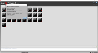
Now, I want to test RF feature on my custom board. SmartRF Studio can detect my MCU but it gives the attached error when I try to connect. I also tried to connect another launchpad with the same debugger and no problem with that. 

I will be grateful if some can help.

Regards.

  • Hi Metehan,

    Did you disconnect from the software programming tool after flashing the image?  It is important for the XDS110 to not be accessed by any other tools while attempting to connect with Smart RF Studio.  Please note that no firmware is required to use SmartRF Studio with the SimpleLink devices, as even a blank device can be operated with this software.  Please try to disconnect and re-connect your hardware to verify that the XDS110 is not being otherwise accessed.

    Next, please make sure that the LP-CC2652RB jumpers are completely disconnected from the on-board CC2652RB device so that you can properly connect to the external CC2652R7.  You can review the Using the LaunchPad to Debug & Program External Devices section of the LaunchPad Getting Started Guide.

    Regards,
    Ryan

  • Hi Ryan,

    Yes, I disconnect all other tools before trying to connect SmartRF. I also tried disconnect and re-connect as you said. 


    All jumpers on LP-CC2652RB are disconnected. I tried both powering my custom board from XDS110 and powering from external source (in both cases connected power jumper on related positions) but it did not solve my issue.

    I even tried latest version of SmartRF studio but still no connection. 

    Regards.

  • Thanks for running those tests.  Here are some relevant E2E threads:

    https://e2e.ti.com/f/1/t/1034116 
    https://e2e.ti.com/f/1/t/997769 

    It is likely a JTAG instability issue which should be resolved through the hardware.  You can submit your design to SIMPLELINK-2-4GHZ-DESIGN-REVIEWS for further review.

    Regards,
    Ryan

  • Hi Ryan,

    As you said, we submitted our design and looking for news from TI. Thanks for your interest.

    Regards,

    Metehan

  • Hi Metehan,

    I'm working to complete the schematic and layout review you requested.

    In terms of the JTAG portion, I don't see any specific areas of concern that would lead to the connection issue described above. However items to double check would be:

    • Verify the ground connection between your board and the XDS110 board. If there is not a good ground connection then communication would be impacted
    • Use the shortest length of wiring possible between the two boards
    • To improve noise immunity it may be desirable to add pull-up resistors to the JTAG lines

    I will follow up with additional comments on the schematic and layout via email.

    Best Regards,

    Jake

  • Hi Jake and Ryan,

    We examined hardware design review report that you send via e-mail. 

    Use the shortest length of wiring possible between the two boards

    Trying this solution you suggested has become quite beneficial for JTAG interface. We are able to flash the board up to 10Mhz of TCLK frequency now. I think JTAG problem is solved. 

    But when it comes to RF part, we are still not able to connect SmartRF Studio (same error at the top of this post). Also we try RfPacketTx example from  SimpleLink CC13xx CC26xx SDK (6.10.00.29) but code get stuck in RF_runCmd. I guess this happens because there is no response from RF core.


    On the other hand we tried OSCHF_DebugGetCrystalAmplitude and OSCHF_DebugGetExpectedAverageCrystalAmplitude functions. OSCHF_DebugGetCrystalAmplitude returns 0  and OSCHF_DebugGetExpectedAverageCrystalAmplitude returns 465. 

    We checked 48 MHz oscillator and even replaced it with a new one. Part number of oscillator we use is Kyocera CX2016DB48000C0FPLC1. I think it satisfies the requirements in MCU datasheet. 

    Do you have recommendations regarding these information to get SmartRF Studio working? 

    Regards, 

    Metehan

  • Hi Metehan,

    Please review the footprint you're using for the 48MHz crystal. I went back and looked at the files that you sent and it looks like the footprint is mirrored as compared to the datasheet specification. This can happen when the "bottom" view and "top" view get mixed up during foot print layout.

    -Jake

  • Hi Jake,

    Yes, the footprint was mirrored. We somehow managed to solder crystal correctly and now it works and we are able to communicate using both SmartRF and example code.

    Thanks a lot for your help. 


    Regards,

    Metehan