This thread has been locked.

If you have a related question, please click the "Ask a related question" button in the top right corner. The newly created question will be automatically linked to this question.

CC1200: The RF module goes in IDLE state and does not recover. What can be the possible reason and how to recover it?

Part Number: CC1200

We have configured CC1200 to transmit periodically every 250ms and it is also configured in sniff mode to receive packets from air. After running successfully for about an hour, while switching between sniff mode to TX mode, the RF enters into IDLE state and even after 2-3 retries, it does not recover itself. I tried changing the state forcefully to IDLE and then to TX again, but that did not work either. So, I am neither able to receive any packets or transmit any packets.

What can be the possible reason for this behavior and how can i prevent it? I observed the only way to recover was by power cycle, how else can i recover it?

  • How do you know that it is in IDLE state? Have you read the MARCSTATE register?

    If you for some reason have gotten an RX overflow situation or TX FIFO underflow, you will not be able to enter RX or TX again without Flushing the relevant FIFO.

    Without knowing your register settings and how exactly you are doing error handling and switching between RX and TX in SW, it is not possible to tell exactly what is causing this.

    Siri

  • Yes i read the MARCSTATE register and got to know it is in IDLE state. I checked for FIFO ERROR situations too, its not that.

    In SW, I am switching directly between TX and EWOR. The RF is always in Sniff Mode and receives packets when RXFIFO_THR_PKT (0x01) Interrupt is received. We transmit every 250ms after switching the state to TX and change state to EWOR after TX completion

    Below is the register settings used - 

    static const stRegSettings g_stPreferredSettings[] =
    {
            {CC1200_IOCFG2,            0x29}, //sync detect
            {CC1200_IOCFG0,            0x01}, //RX fifo threshold + End of packet
            {CC1200_SYNC3,             0xF0},
            {CC1200_SYNC2,             0xCC},
            {CC1200_SYNC1,             0xF0},
            {CC1200_SYNC0,             0xCC},
            {CC1200_SYNC_CFG1,         0xA8},
            {CC1200_SYNC_CFG0,         0x13},
            {CC1200_DEVIATION_M,       0x68},
            {CC1200_MODCFG_DEV_E,      0x04},
            {CC1200_DCFILT_CFG,        0x26},
            {CC1200_PREAMBLE_CFG0,     0x8A},
            {CC1200_IQIC,              0x00},
            {CC1200_CHAN_BW,           0x82},
            {CC1200_MDMCFG1,           0x42},
            {CC1200_MDMCFG0,           0x05},
            {CC1200_SYMBOL_RATE2,      0x7F},
            {CC1200_SYMBOL_RATE1,      0x75},
            {CC1200_SYMBOL_RATE0,      0x10},
            {CC1200_AGC_REF,           0x2A},
            {CC1200_AGC_CS_THR,        0x01},
            {CC1200_AGC_CFG1,          0x16},
            {CC1200_SETTLING_CFG,      0x03},
            {CC1200_FIFO_CFG,          0x5F}, //FIFO level 63 -> 0x3F //95 -> 0x5F
            {CC1200_FS_CFG,            0x12},
            {CC1200_WOR_CFG0,          0x20},
            {CC1200_WOR_EVENT0_LSB,    0x67},
            {CC1200_PKT_CFG2,          0x00},
            {CC1200_PKT_CFG1,          0x00},
            {CC1200_PKT_CFG0,          0x20},
            {CC1200_RFEND_CFG0,        0x04},
            {CC1200_PA_CFG0,           0x55},
            {CC1200_PKT_LEN,           0xFF},
            {CC1200_IF_MIX_CFG,        0x18},
            {CC1200_TOC_CFG,           0x03},
            {CC1200_MDMCFG2,           0x00},
            {CC1200_FREQ2,             0x5B},
            {CC1200_FREQ1,             0x99},
            {CC1200_FREQ0,             0x99},
            {CC1200_IF_ADC1,           0xEE},
            {CC1200_IF_ADC0,           0x10},
            {CC1200_FS_DIG1,           0x07},
            {CC1200_FS_DIG0,           0xAB},
            {CC1200_FS_CAL1,           0x40},
            {CC1200_FS_CAL0,           0x0E},
            {CC1200_FS_DIVTWO,         0x03},
            {CC1200_FS_DSM0,           0x33},
            {CC1200_FS_DVC0,           0x17},
            {CC1200_FS_PFD,            0x00},
            {CC1200_FS_PRE,            0x6E},
            {CC1200_FS_REG_DIV_CML,    0x1C},
            {CC1200_FS_SPARE,          0xAC},
            {CC1200_FS_VCO4,           0x13},
            {CC1200_FS_VCO2,           0x64},
            {CC1200_FS_VCO1,           0xAC},
            {CC1200_FS_VCO0,           0xB5},
            {CC1200_IFAMP,             0x0D},
            {CC1200_XOSC5,             0x0E},
            {CC1200_XOSC1,             0x03},
    };

  • It is still not clear to me how your code is failing. 

    You say " the RF enters into IDLE state and even after 2-3 retries, it does not recover itself." What do you mean by that?

    The radio will enter IDLE state both after you transmit a packet and after you receive a packet, so there is nothing wrong with that.

    Is the problem that it is not getting out of IDLE? If so, when does this happens (when strobing STC, Strobing SWORD, after receiving a packet?)

    I will need so know what you are doing in the code, to see if I can understand what goes wrong. I do not need your entire application code, but need to know how and when you are changing between states, and also how you are handling incoming packets (what interrups are you using, what do you do in the ISR etc.)

    Siri

  • I am receiving packets and transmitting packets successfully for about an hour.

    For each transmission, i am filling TX FIFO with required data and changing the RF state to TX by strobing STX. Then i am checking the Marc state if it is actually in TX mode. 

    You are right, i mean to say, even after strobing STX, the RF state is not changing and there is no transmission.

  • Are you checking the MARCSTATE BEFORE you strobe STX?

    I am afraid I cannot say what goes wrong if I do not have your code. 

    I have never heard of a problem related to getting into TX state, unless you are coming from an Error state that has not been handled properly.

    That is, if you have entered an overflow/underflow state and you simply Strobe IDLE to get out of it instead of flushing the FIFO, there might be problems with the FIFO pointers when trying to transmit the next packet.

    What is the value of the TXFIRST, TXLAST, NUM_TXBYTES, FIFO_NUM_TXBYTES before and after you try to send the packet which is not sent?

    Siri

  • We are reading the MARCSTATE after strobing STX.

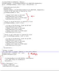
    This is the Code snippet for TX mode.

    The first arrow is from where i am seeing the MARCSTATE as IDLE

    The second part is where i get stuck till there is a watchdog reset or power cycle. There is always 1byte left in TX FIFO which i thought is because the RF state is IDLE.

  • I am afraid I do not follow the flow of your code.

    For instance, the (FailureCount < 3) on line 3, what is that? A comment? There seems to be missing a operator.

    Also, you should not use all these delays in the code. Why are you waiting 45 us to check if the chip is in IDLE, when you have just issued a STX strobe?


    Your TX code should simply do something like shown below when wanting to go to TX.

    I will here assume that you do not know id the radio is IDLE, in SLEEP or in RX state when you decide to enter TX.

    • Strobe IDLE
    • Wait for MARCSTATE reporting IDLE
    • Strobe SFRX
    • Strobe SFTX
      • At this point you know that the radio is in IDLE and that your FIFOs are empty and that the FIFO pointers are OK
    • Write your packet to the FIFO.
      • You have configured the radio for variable packet length mode, so write the length byte as the first byte: for example 0x05, 0x01, 0x02, 0x03, 0x04, 0x05 (length byte, + 5 payload bytes)
    • Strobe STX
    • Wait for the packet to be sent
      • It is recommended that you have programmed one of the GPIO signals to be PKT_SYNC_RXTX, so that you can simply wait for a falling edge on this signal, indicating that a packet has been sent.

    At this point, your TX FIFO should be empty (if you have written the packet length correctly)

    When the packet is sent, you can go back to eWOR

    BR

    Siri

  • Yes, sorry in line 3 i have missed && operator. it goes:

    while( ((SPIRegAccessResp & 0x1F)!= 0x13) && (FailureCount < 3))

    After filling the tx fifo, i strobe STX and wait 45us (in datasheet tx to rx and viceversa time is mmentioned as 45us, so i am giving this delay). Then i am reading the marcstate to check if its reporting tx. if not i am checking if it is in idle or in any of the fifo error condition

  • It might take 35 us to go from RX to TX, but how would you know that you are in RX. You could just as well be in SLEEP, in the middle of reseption so that your FIFO has started to fill up, or in IDLE (just having received a packet).

    I strongly recommend that you force the device into IDLE between changing states, and take care of the FIFO pointers by flushing the FIFOs BEFORE entering TX. Checking for errors after you have strobed TX is not the way to go.

    Siri

  • I am modifying the code according to your suggestion.

    In case, RF doesnt enter TX mode and remains in IDLE state, what is the possible time and method of recovery? 

  • I have supported this device since it was launched, and I have never experienced that it will not enter TX from IDLE state. If you have an unhandled error state and force the device into IDLE instead of flushing the FIFO with the reported error, I cannot say what is happening. This is why I would recommend that you do the flushing as described in my previous post.

  • I followed all the methods you mentioned but i am still facing the issue. Can you suggest anything more please to help us fix this

  • As I am not able to reproduce this error in any way, and this is a problem I have never heard of before, I am not sure how to proceed.

    To be able to get any further, you would either have to be able to make a SW code that can reproduce the error on our dev kit (CC1120EM + TRXEB), or you need to have a logic analyzer connected to the device, monitoring all SPI lines and the GPIO signals, when it is failing, so that we can understand what exactly is going on before the device gets into this state.

    BR

    Siri