This thread has been locked.

If you have a related question, please click the "Ask a related question" button in the top right corner. The newly created question will be automatically linked to this question.

CC1310: E70-915T30S - CC1310 with PA front end RF problem.

Part Number: CC1310
Other Parts Discussed in Thread: CC1190

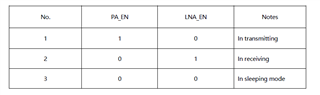
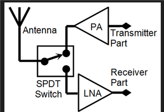
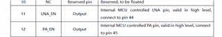
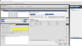
Hi All, we are currently working with E70-915T30S modules from the manufacturer ebyte, these modules come with their own firmware, but we run a custom firmware on them, we have had problems when performing this integration, we see that we do not get the desired powers and not the required distance, to solve this, I would like to know how to properly configure SmartRF Studio 7 to use the RF stage of the CC1310 + a power amplifier. As we could observe, the E70-915T30S uses a BT33L as PA, but we don't know if it is necessary to use the PA and LNA pins or other configurations.

Regards

Francisco

  • Hi,

    You should contact the module manufacture directly for support for their product.

    Can you provide the schematic for the ebyte module ?

    In order to debug the output power, first measure the output power from the CC1310 at the 50 ohm point with the BT33L disconnected.

    Regards,

       Richard

  • Hi Richard, yes, I contact the manufacturer, but they don´t give us support about our problem because we use our own code. Assuming our device it´s not working properly and assuming that the power amplifier is different (not CC1190 because ebyte performs up to 30dBm output) what will be the recommended configuration in smartRF studio for a CC1310 with an external PA? the standalone CC1310 configuration? or we need to use CC1310-90 configuration with changes?

    they give that logic table for PA_EN and LNA_EN

    cheers;

    Francisco

  • Do you have a schematic ?

  • not, we only know that they use a BT33L as PA.

  • The BT33L is just a fixed gain amplifier with the gain set by the passives connected to pins 1 and 18 on BT33L.

    There must be a SPDT switch on your module. This needs to be set otherwise you will get approx 20-25 dB of IL. 

    In SmartRF studio, you just need to send an unmodulated Tx carrier. I would set the output power level to 10 dBm to start with.

    What output power are you running the module at ?

    What output power are you measuring ?

  • Dear Richard, when you say that the module must have an SPDT switch, you´re talking about something like this? :

    ebyte say they use pin 11 and 12 for LNA and PA (DIO_6 and DIO_7)

    so, this will be the recommended configuration?

  • Yes. Just turn the output power setting down slightly since the BTS33 has a gain around 20-22 dB. You should need a power setting some where around 8 dBm +/- 2 dB.

  • Hi Richard, inside code composer studio, do we need to make a change to enable PA and LNA control? thank you for your support.

    These are the examples used for us.

  • Hi,

    CC1310 has no switch so the switch control must be added for your module.

  • Hi Richard, yes, you´re right, I cant now make the correct PA and LNA activation (using some pins inside the module), but when I perform some basic distance tests, the reception is not good, we are using three devices, one E70 is the sender and two devices are receivers (one E70 and other CC1310 Launchpad), the launchpad as a reception over 600 meters without line sight but E70 can´t breach the 200 meters reception. what could be the problem? we are also using

    #define SET_CCFG_MODE_CONF_SCLK_LF_OPTION            0x0        // LF clock derived from High Frequency XOSC

    because E70 hasn't external crystal soldered.

    What could be the cause of the poor reception quality?

  •        
    There are many factors that can cause poor range. In order to determine the root cause, please follow the guidelines shown below to debug the root cause:
           
    Calculate the theoretical range:
           
    1 Read "Achieving Optimum Range" describes the important parameters so realistic values are entered in the range spreadsheet.
           
    2 Calculate line-of-sight (LOS) range in the spreadsheet with your radio settings  
      - output power
      - selection of chip and datarate
      - height of antennas above ground
      - operating frequency
           
    3 Are there any objects between the LOS of the transmitter and receiver ? 
      - If so, add a suitable absorbtion material that can represent the object blocking the LOS.
           
    4 Choose an antenna gain that is realistic for your product
      - For example: achieving 100% efficiency for handheld device at 433 MHz will never occur. Typical efficiency would be -4 dBi for a good 433 MHz antenna for a handheld product. 
           
    If the range is not meeting the expected distance then the root cause needs to be determined:
           
    Poor range could be caused by one or more of the following factors:
      - Poor sensitivity in the receiver
      - Poor Tx output power
      - Poor antenna
           
    The measurement methods will depend on what type of equipment is available. 
           
    5 Measure the conducted sensitivity 
      - Disconnect the antenna and perform conducted measurements at the SMA connector or solder a semi-rigid cable at the 50 ohm point.
      - Preferred: use a signal generator that is capable to send data packets. If the signal generator cannot send data packets then just send preamble data.
        If a signal generator is not available, then use an EM with attenuation between the EM SMA connector and the antenna connector on the customer board. 
        - It is difficult to get accurate numbers using this method since the exact values of output power and attenuation are not known. 
        - Some energy will also travel over the air from the EM so placing the receiver in a metal box to shield it will give more accurate results.
      - If the conducted sensitivity is poor: 
        - Are the settings the same as the recommended values in SmartRF studio?
        - Is the schematic according to the reference design?
        - Is the layout according to the reference design?
           
    6 Measure the conducted output power 
      - Disconnect the antenna and perform conducted measurements at the SMA connector or solder a semi-rigid cable at the 50 ohm point.
      - Preffered: use a spectrum analyzer (MSP-SA430 or similar does not have the required accuracy)
      - If a SA is not available, then use an EM or LaunchPad with a SMA connection point.
        - Add a known RF attenuation block between the transmiter's SMA connector and the EM / LaunchPad connector. 
        - Use SmartRF Studio and set the EM / LaunchPad in continuous RX, and read the RSSI.
      - If the conducted power is poor:
        - Is the schematic according to the reference design?
        - Is the layout according to the reference design?
           
    7  Measure the antenna. If the sensitivity and output power are as expected and the range is poor compared to the theoretical range the antenna efficiency is most likely poor. 
      - Preffered: use a network analyzer (VNA) to accurately tune the antenna.  
        - Disconnect the radio and add a semi-rigid cable / SMA connector at the 50 ohm point towards the antenna matching network and antenna.
        - Compensate the semi-rigid cable or SMA with port extensions so they are not included in the antenna measurements.
        - Always measure the antenna in the final casing otherwise the tuning will be invalid.
        - Always measure the antenna as would be used in the application. If the device is placed on a metal shelf, then the tuning must be made in a similiar environment.
        - Measure the resonance of the antenna and make sure the matching is better than VSWR 2.
        -  If the resonance is not correct or the matching is greater than VSWR 2, then the antenna design needs to be reviewed again. 
      - If measurements with a VNA is not possible then use an EM or LaunchPad with an known good antenna.
        - Measure the resonance frequency by sweeping the frequency of the transmitter and measure which frequency the receiver reads the highest RSSI. 
      - If the antenna is poor:
        - Is the antenna matching network same as the antenna reference design?
        - Is the antenna layout according to a known antenna reference design?
  • Hi Richard, from ebyte, they reply me about the reception problem: "Problem could be frequency bais (I think they want to say bias) of the main Crystal", do you know what could be a problem like this?
  • Hi,

    Have you measured the frequency offset which indirectly measures how well you have tuned the crystal?

    Transmit a Tx unmodulated carrier at 868.000 MHz and then measure the frequency offset on a spectrum analyzer. Measure the frequency offset from 868.000 MHz on the spectrum analyzer. It should be less than 17 kHz offset and ideally just a couple of kHz offset. 

    Regards,

       Richard