This thread has been locked.

If you have a related question, please click the "Ask a related question" button in the top right corner. The newly created question will be automatically linked to this question.

CC1312R7: Unable to create a working solution for swapping RX and TX pins of UART1 module by Sysconfig within CCS

Part Number: CC1312R7
Other Parts Discussed in Thread: , SYSCONFIG

Hi,

I have created my own board using CC1312R7, which - among other peripherals - also contains a CP2102N-A02-GQFN28R USB transceiver. Unfortunately I have connected the UART_TX of the MCU to the UART_TX of the USB transceiver (and I did the same for the UART_RX pins).

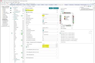
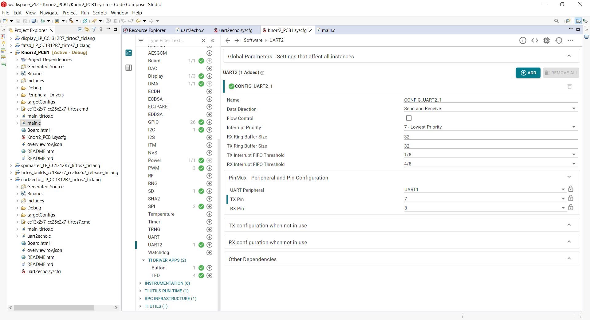
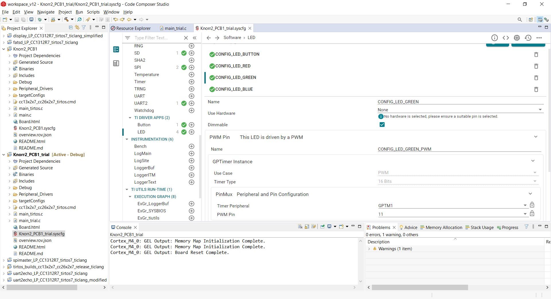
My first thought was - because I didn't want to cut and re-wire trances right away - can I remap the pins in software instead? In my project, I have used simplelink_cc13xx_cc26xx_sdk_6_30_01_03, creating the configuration with Sysconfig. I am using the UART1 peripheral for sending debug strings to the PC. I am using the XDS110 debugger from an LP-CC1312R7 to program/debug my hardware. I am also using a logic analyzer with protocol decoder to see the data traffic. In the code, I am using the Display driver (UART mode) from TI Drivers to utilize the realized "printf"-like functions. With the original Sysconfig values: Display\UART\PinMux\TX Pin = 8 and Display\UART\PinMux\RX Pin = 7 I can see the correct debug string being sent to pin 8 (DIO3) with the logic analyzer, despite of the wrong wiring in my PCB. WHen I reverse the pin mapping to: Display\UART\PinMux\TX Pin = 7 and Display\UART\PinMux\RX Pin = 8, then I can detect no bytes being sent on either of the MCU pins (I am monitoring both). I thought, that this may be due to the wrong wiring in the hardware, so I configured the RX and TX pins to currently unused pins, which are wired to only testpoints in the hardware. This configuration has worked (I can see the string with logic analyzer on pin 39): Display\UART\PinMux\TX Pin = 39 (DIO26) and Display\UART\PinMux\RX Pin = 40 (DIO27). However, when I reverse these two pins as well: Display\UART\PinMux\TX Pin = 40 (DIO27) and Display\UART\PinMux\RX Pin = 39 (DIO26), nothing can be seen on either of those pins with the logic analyzer.

I have traced back the content of the generated files under SysConfig, and they always seem to reflect the right configuration of pins, handles, etc.

Do I skip over something crucial so that some of the remap-configurations don't work? What could be the reason?

I have attached the complete project with all the files withing in both working and non-working cases. Never mind the rest of the code in main.c, it just writes and reads out some bytes to/from an onboard RTCC IC over I2C (which works by the way).

I would be grateful for some advice on what I should try to solve this problem.

I was also trying to re-map the UART pins of the CC1312R7 launchpad hardware using the SDK example project: "uart2echo_LP_CC1312R7_tirtos7_ticlang". I succeeded, but this example project does not use the TI Display middleware. Does this mean that my problem lies somewhere with the middleware too?

Thank you and Best Regards:

Balazs

K2_PCB1_Doesnt_Work.zipK2_PCB1_Works.zip

  • Unfortunately I was not able to open up your project, but I did some testing with the CC1312R7LP and the display driver (using the UART).

    I used the default display code example from the latest SDK and changed the UART to use some available pins (DIO26 and DIO27) instead of using the the XSC110 UART (DIO2 and DIO3):

    The following changes were made in sysconfig:

    I tested both:

    TX on DIO26

    RX on DIO27 

    and the other way around, and were able to monitor data out (TX) on both DIO26 and DIO27.

    The application code was simplified as follows:

    void *mainThread(void *arg0)
    {
        Display_init();
    
        Display_Params params;
        Display_Params_init(&params);
        params.lineClearMode = DISPLAY_CLEAR_BOTH;
    
    
        Display_Handle hSerial = Display_open(Display_Type_UART, &params);
    
        if (hSerial == NULL)
        {
            /* Failed to open a display */
            while (1) {}
        }
    
        while(1)
        {
            Display_printf(hSerial, 0, 0, "UUUUUUUUUUUU"); // 0x55555555------
            usleep(1000);
        }
    }

    BR

    Siri

  • Hi Siri,

    Thank you for your response, I really appreciate that you took the time to analyze this.

    Your approach gave me an idea. I have now tried to run the SDK example called "uart2echo" (TI-RTOS7\TI Clang Compiler) on my hardware, where the RX and TX of the UART is wired incorrectly to the CP2102. I took the example code as is, changed the pins from: UART TX = DIO3 and UART RX = DIO2 to UART TX = DIO2 and UART RX = DIO3, and these new assignments, the program runs on my hardware correctly (echoing all characters). This was great news, because this means that my hardware can be used with those pins switched. The settings in sysconfig are:

    the example code's modified SysConfig

    I went back to my own code afterwards, checked the sysconfig settings again, and applied them, and the code does not work. The sysconfig settings for my code are:

    My own code's SysConfig

    You can see that many other pins and peripherals are also configured to suit the board's functions later. The relevant pins here for the UART however, are identically configured compared to the example above. DIO2 is pin 7 and DIO3 is pin 8 on the MCU. Why is this configuration not working on the same hardware, while the modified example code does work on the same hardware?

    I have attached my code's main.c file, as well as the code view of the syscfg files for both projects.

    Thank you very much, Best Regards:

    Balazs

    2742.main.c
    /*
     * Copyright (c) 2015-2019, Texas Instruments Incorporated
     * All rights reserved.
     *
     * Redistribution and use in source and binary forms, with or without
     * modification, are permitted provided that the following conditions
     * are met:
     *
     * *  Redistributions of source code must retain the above copyright
     *    notice, this list of conditions and the following disclaimer.
     *
     * *  Redistributions in binary form must reproduce the above copyright
     *    notice, this list of conditions and the following disclaimer in the
     *    documentation and/or other materials provided with the distribution.
     *
     * *  Neither the name of Texas Instruments Incorporated nor the names of
     *    its contributors may be used to endorse or promote products derived
     *    from this software without specific prior written permission.
     *
     * THIS SOFTWARE IS PROVIDED BY THE COPYRIGHT HOLDERS AND CONTRIBUTORS "AS IS"
     * AND ANY EXPRESS OR IMPLIED WARRANTIES, INCLUDING, BUT NOT LIMITED TO,
     * THE IMPLIED WARRANTIES OF MERCHANTABILITY AND FITNESS FOR A PARTICULAR
     * PURPOSE ARE DISCLAIMED. IN NO EVENT SHALL THE COPYRIGHT OWNER OR
     * CONTRIBUTORS BE LIABLE FOR ANY DIRECT, INDIRECT, INCIDENTAL, SPECIAL,
     * EXEMPLARY, OR CONSEQUENTIAL DAMAGES (INCLUDING, BUT NOT LIMITED TO,
     * PROCUREMENT OF SUBSTITUTE GOODS OR SERVICES; LOSS OF USE, DATA, OR PROFITS;
     * OR BUSINESS INTERRUPTION) HOWEVER CAUSED AND ON ANY THEORY OF LIABILITY,
     * WHETHER IN CONTRACT, STRICT LIABILITY, OR TORT (INCLUDING NEGLIGENCE OR
     * OTHERWISE) ARISING IN ANY WAY OUT OF THE USE OF THIS SOFTWARE,
     * EVEN IF ADVISED OF THE POSSIBILITY OF SUCH DAMAGE.
     */
    
    /*
     *  ======== main.c ========
     */
    
    /* For usleep() */
    #include <unistd.h>
    #include <stdint.h>
    #include <stddef.h>
    
    /*
     *  ======== fatsd.c ========
     */
    #include <file.h>
    #include <stdbool.h>
    #include <stdio.h>
    #include <stdlib.h>
    #include <string.h>
    #include <time.h>
    
    /* POSIX Header files */
    #include <pthread.h>
    
    #include <third_party/fatfs/ffcio.h>
    
    /* Driver Header files */
    #include <ti/drivers/GPIO.h>
    #include <ti/drivers/I2C.h>
    #include <ti/drivers/SPI.h>
    #include <ti/display/Display.h>
    #include <ti/drivers/SDFatFS.h>
    //#include <ti/drivers/Watchdog.h>
    
    /* Driver configuration */
    #include "ti_drivers_config.h"
    
    // Peripheral drivers
    #include "PCF8523_RTCC.h"
    
    /* Buffer size used for the file copy process */
    #ifndef CPY_BUFF_SIZE
        #define CPY_BUFF_SIZE 2048
    #endif
    
    /* String conversion macro */
    #define STR_(n) #n
    #define STR(n)  STR_(n)
    
    /* Drive number used for FatFs */
    #define DRIVE_NUM 0
    
    const char inputfile[]  = "fat:" STR(DRIVE_NUM) ":input.txt";
    const char outputfile[] = "fat:" STR(DRIVE_NUM) ":output.txt";
    
    const char textarray[]
        __attribute__((aligned(4))) = "***********************************************************************\n"
                                      "0         1         2         3         4         5         6         7\n"
                                      "01234567890123456789012345678901234567890123456789012345678901234567890\n"
                                      "This is some text to be inserted into the inputfile if there isn't\n"
                                      "already an existing file located on the media.\n"
                                      "If an inputfile already exists, or if the file was already once\n"
                                      "generated, then the inputfile will NOT be modified.\n"
                                      "***********************************************************************\n";
    /* Set this to the current UNIX time in seconds */
    const struct timespec ts = {.tv_sec = 1469647026, .tv_nsec = 0};
    
    /* File name prefix for this filesystem for use with TI C RTS */
    char fatfsPrefix[] = "fat";
    
    unsigned char cpy_buff[CPY_BUFF_SIZE] __attribute__((aligned(4)));
    
    static uint8_t slaveAddress;
    static Display_Handle display;
    
    #define SPI_MSG_LENGTH 30
    #define IMU_SPI_READ 0x80
    
    /*
     *  ======== mainThread ========
     */
    void *mainThread(void *arg0)
    {
        /* 1 second delay */
        uint32_t time = 1;
    
        uint8_t I2C_txBuffer[21];
    	uint8_t I2C_rxBuffer[20];
    
    	unsigned char IMUrxBuffer[SPI_MSG_LENGTH];
    	unsigned char IMUtxBuffer[SPI_MSG_LENGTH];
    
    	I2C_Handle i2c;
    	I2C_Params i2cParams;
    	I2C_Transaction i2cTransaction;
    
    	SPI_Handle IMUspi;
    	SPI_Params IMUspiParams;
    	SPI_Transaction IMUtransaction;
    	bool IMUspiTransferOK;
    
    	SDFatFS_Handle sdfatfsHandle;
    	/* Variables for the CIO functions */
    	FILE *src, *dst;
    	/* Variables to keep track of the file copy progress */
    	unsigned int bytesRead    = 0;
    	unsigned int bytesWritten = 0;
    	unsigned int filesize;
    	unsigned int totalBytesCopied = 0;
    	/* Return variables */
    	int result;
    
        /* Call driver init functions */
        GPIO_init();
        I2C_init();
        SPI_init();
        SDFatFS_init();
        // Watchdog_init();
    
        /* Open the UART display for output */
    	display = Display_open(Display_Type_UART, NULL);
    	if (display == NULL)
    	{
    		while (1)
    		{
    			sleep(time);
    			GPIO_toggle(CONFIG_LED_GREEN);
    		}
    	}
    
        /* Configure the LED pin */
        GPIO_setConfig(CONFIG_LED_GREEN, GPIO_CFG_OUT_STD | GPIO_CFG_OUT_LOW);
        GPIO_setConfig(CONFIG_LED_BUTTON, GPIO_CFG_OUT_STD | GPIO_CFG_OUT_LOW);
    
        /* Turn off user LED */
        GPIO_write(CONFIG_LED_GREEN, CONFIG_GPIO_LED_OFF);
    
        /* add_device() should be called once and is used for all media types */
    	add_device(fatfsPrefix,
    			   _MSA,
    			   ffcio_open,
    			   ffcio_close,
    			   ffcio_read,
    			   ffcio_write,
    			   ffcio_lseek,
    			   ffcio_unlink,
    			   ffcio_rename);
    
    	/* Initialize real-time clock */
    	clock_settime(CLOCK_REALTIME, &ts);
    
        Display_printf(display, 0, 0, "Starting i2c.\n");
    
        /* Create I2C for usage */
    	I2C_Params_init(&i2cParams);
    	i2cParams.bitRate = I2C_400kHz;
    	i2c               = I2C_open(CONFIG_I2C_RTCC, &i2cParams);
    	if (i2c == NULL)
    	{
    		Display_printf(display, 0, 0, "Error Initializing I2C\n");
    		while (1)
    		{
    			sleep(time);
    			GPIO_toggle(CONFIG_LED_GREEN);
    		}
    	}
    	else
    	{
    		Display_printf(display, 0, 0, "I2C Initialized!\n");
    		GPIO_write(CONFIG_LED_BUTTON, CONFIG_GPIO_LED_ON);
    		sleep(time);
    		GPIO_write(CONFIG_LED_BUTTON, CONFIG_GPIO_LED_OFF);
    	}
    
    	/* Common I2C transaction setup */
    	i2cTransaction.writeBuf   = I2C_txBuffer;
    	i2cTransaction.writeCount = 1;
    	i2cTransaction.readBuf    = I2C_rxBuffer;
    	i2cTransaction.readCount  = 0;
    
    	i2cTransaction.slaveAddress = PCF8523_I2C_ADDRESS;
    	I2C_txBuffer[0]             = 0x00;
    
    	if (I2C_transfer(i2c, &i2cTransaction))
    	{
    		slaveAddress = PCF8523_I2C_ADDRESS;
    		Display_printf(display, 0, 0, "Detected RTCC with slave address 0x%x", PCF8523_I2C_ADDRESS);
    	}
    	else
    	{
    		i2cErrorHandler(&i2cTransaction, display);
    	}
    
    	if (slaveAddress == 0)
    	{
    		Display_printf(display, 0, 0, "Failed to detect the RTCC!");
    		I2C_close(i2c);
    		while (1)
    		{
    			sleep(time);
    			GPIO_toggle(CONFIG_LED_GREEN);
    		}
    	}
    
    	// send RTCC config
    	I2C_txBuffer[0]				= 0x00;	// start address = 0x00
    	I2C_txBuffer[1]				= 0x00;
    	I2C_txBuffer[2]				= 0x00;
    	I2C_txBuffer[3]				= 0xE0;
    	I2C_txBuffer[4]				= 0x33;	// 33 seconds
    	I2C_txBuffer[5]				= 0x09;	//	9 minutes
    	I2C_txBuffer[6]				= 0x21;	// 21 hours
    	I2C_txBuffer[7]				= 0x03;	// 3 (day: 1...31)
    	I2C_txBuffer[8]				= 0x02;	// Wednesday
    	I2C_txBuffer[9]				= 0x11;	// November
    	I2C_txBuffer[10]			= 0x16; // xx22
    	I2C_txBuffer[11]			= 0x00;	// minute alarm disabled
    	I2C_txBuffer[12]			= 0x00;	// hour alarm disabled
    	I2C_txBuffer[13]			= 0x00; // day alarm disabled
    	I2C_txBuffer[14]			= 0x00;	// weekday alarm disabled
    	I2C_txBuffer[15]			= 0x00;	// offset = 0
    	I2C_txBuffer[16]			= 0x00;	// timer clkout OFF
    	I2C_txBuffer[17]			= 0x07;	// TMR_A_FREQ 1/3600 Hz
    	I2C_txBuffer[18]			= 0x00;	// TMR_A_REG 0
    	I2C_txBuffer[19]			= 0x07;	// TMR_B_FREQ 1/3600 Hz
    	I2C_txBuffer[20]			= 0x00;	// TMR_B_REG 0
    	i2cTransaction.writeCount	= 21;
    	i2cTransaction.readCount	= 0;
    
    	if (I2C_transfer(i2c, &i2cTransaction))
    	{
    		Display_printf(display, 0, 0, "Default configuration written\n");
    	}
    	else
    	{
    		i2cErrorHandler(&i2cTransaction, display);
    	}
    
    	i2cTransaction.writeCount	= 1;
    	i2cTransaction.readCount	= 20;
    
    	if (I2C_transfer(i2c, &i2cTransaction))
    	{
    		Display_printf(display, 0, 0, "Register readout complete\n");
    	}
    	else
    	{
    		i2cErrorHandler(&i2cTransaction, display);
    	}
    
    	I2C_close(i2c);
    	Display_printf(display, 0, 0, "I2C closed!");
    
    
    	// SPI **************************************************************************
    
    	SPI_Params_init(&IMUspiParams);
    	IMUspiParams.frameFormat = SPI_POL0_PHA0;
    	IMUspiParams.bitRate     = 4000000;
    	IMUspi		             = SPI_open(CONFIG_SPI_IMU, &IMUspiParams);
    	if (IMUspi == NULL)
    	{
    		Display_printf(display, 0, 0, "Error initializing IMU SPI\n");
    		while (1) {}
    	}
    	else
    	{
    		Display_printf(display, 0, 0, "IMU SPI initialized\n");
    	}
    
    	IMUtxBuffer[0] = 0x75 | IMU_SPI_READ;	// 0x75 = WHO_AM_I; Read bit set to "1" (read)
    	IMUtxBuffer[1] = 0x00;
    
    
    	IMUtransaction.count = 2;						// we just read one byte, which should be 0x42 of value
    	IMUtransaction.txBuf = (void *)IMUtxBuffer;
    	IMUtransaction.rxBuf = (void *)IMUrxBuffer;
    
    	// Hardware CS handling only works in PHA1 SPI mode settings, otherwise it gets de-asserted between bytes. See here:
    	// https://e2e.ti.com/support/wireless-connectivity/sub-1-ghz-group/sub-1-ghz/f/sub-1-ghz-forum/1175551/cc1352p-spi-cs-get-s-deasserted-between-bytes/4429425?tisearch=e2e-sitesearch&keymatch=minDmaTransferSize#4429425
    	// Also mind the TI driver's DMA mode, and Min DMA Transfer Size setting in SysConfig. Set it to lower or equal to your lowest SPI frame,
    	// otherwise, CS De-assertion between bytes.
    	// Solution: Control CS from Software...
    
    	/* Perform SPI transfer */
    	// De-assert IMU CS
    	GPIO_write(CONFIG_GPIO_SPI_IMU_CS, 0);
    	IMUspiTransferOK = SPI_transfer(IMUspi, &IMUtransaction);
    	// assert IMU CS
    	GPIO_write(CONFIG_GPIO_SPI_IMU_CS, 1);
    	if (IMUspiTransferOK)
    	{
    		Display_printf(display, 0, 0, "Received from IMU: %s", IMUrxBuffer);
    	}
    	else
    	{
    		Display_printf(display, 0, 0, "Unsuccessful IMU SPI transfer");
    	}
    
    	// SD Card ************************************************************************
    
    	Display_printf(display, 0, 0, "Starting the fatsd example\n");
    	Display_printf(display, 0, 0, "This example requires a FAT filesystem on the SD card.\n");
    	Display_printf(display, 0, 0, "You will get errors if your SD card is not formatted with a filesystem.\n");
    
    	/* Mount and register the SD Card */
    	sdfatfsHandle = SDFatFS_open(CONFIG_SD_0, DRIVE_NUM);
    	if (sdfatfsHandle == NULL)
    	{
    		Display_printf(display, 0, 0, "Error starting the SD card\n");
    		while (1) {}
    	}
    	else
    	{
    		Display_printf(display, 0, 0, "Drive %u is mounted\n", DRIVE_NUM);
    	}
    
    	/* Try to open the source file */
    	src = fopen(inputfile, "r");
    	if (!src)
    	{
    		Display_printf(display, 0, 0, "Creating a new file \"%s\"...", inputfile);
    
    		/* Open file for both reading and writing */
    		src = fopen(inputfile, "w+");
    		if (!src)
    		{
    			Display_printf(display, 0, 0, "Error: \"%s\" could not be created.\n", inputfile);
    			Display_printf(display, 0, 0, "Aborting...\n");
    			while (1) {}
    		}
    
    		fwrite(textarray, 1, strlen(textarray), src);
    		fflush(src);
    
    		/* Reset the internal file pointer */
    		rewind(src);
    
    		Display_printf(display, 0, 0, "done\n");
    	}
    	else
    	{
    		Display_printf(display, 0, 0, "Using existing copy of \"%s\"\n", inputfile);
    	}
    
    	/* Create a new file object for the file copy */
    	dst = fopen(outputfile, "w");
    	if (!dst)
    	{
    		Display_printf(display, 0, 0, "Error opening \"%s\"\n", outputfile);
    		Display_printf(display, 0, 0, "Aborting...\n");
    		while (1) {}
    	}
    	else
    	{
    		Display_printf(display, 0, 0, "Starting file copy\n");
    	}
    
    	/*
    	 * Optional call to disable internal buffering. This allows FatFs to use
    	 * multi-block writes to increase throughput if applicable. Note that this
    	 * may come with a performance penalty for smaller writes.
    	 */
    	result = setvbuf(dst, NULL, _IONBF, 0);
    	if (result != 0)
    	{
    		Display_printf(display, 0, 0, "Call to setvbuf failed!");
    	}
    
    	/*  Copy the contents from the src to the dst */
    	while (true)
    	{
    		/*  Read from source file */
    		bytesRead = fread(cpy_buff, 1, CPY_BUFF_SIZE, src);
    		if (bytesRead == 0)
    		{
    			break; /* Error or EOF */
    		}
    
    		/*  Write to dst file */
    		bytesWritten = fwrite(cpy_buff, 1, bytesRead, dst);
    		if (bytesWritten < bytesRead)
    		{
    			Display_printf(display, 0, 0, "Disk Full\n");
    			break; /* Error or Disk Full */
    		}
    
    		/*  Update the total number of bytes copied */
    		totalBytesCopied += bytesWritten;
    	}
    
    	fflush(dst);
    
    	/* Get the filesize of the source file */
    	fseek(src, 0, SEEK_END);
    	filesize = ftell(src);
    	rewind(src);
    
    	/* Close both inputfile[] and outputfile[] */
    	fclose(src);
    	fclose(dst);
    
    	Display_printf(display,
    				   0,
    				   0,
    				   "File \"%s\" (%u B) copied to \"%s\" (Wrote %u B)\n",
    				   inputfile,
    				   filesize,
    				   outputfile,
    				   totalBytesCopied);
    
    	/* Now output the outputfile[] contents onto the console */
    	dst = fopen(outputfile, "r");
    	if (!dst)
    	{
    		Display_printf(display, 0, 0, "Error opening \"%s\"\n", outputfile);
    		Display_printf(display, 0, 0, "Aborting...\n");
    		while (1) {}
    	}
    
    	/* Print file contents */
    	while (true)
    	{
    		/* Read from output file */
    		bytesRead = fread(cpy_buff, 1, CPY_BUFF_SIZE, dst);
    		if (bytesRead == 0)
    		{
    			break; /* Error or EOF */
    		}
    		cpy_buff[bytesRead] = '\0';
    		/* Write output */
    		Display_printf(display, 0, 0, "%s", cpy_buff);
    	}
    
    	/* Close the file */
    	fclose(dst);
    
    	/* Stopping the SDCard */
    	SDFatFS_close(sdfatfsHandle);
    	Display_printf(display, 0, 0, "Drive %u unmounted\n", DRIVE_NUM);
    
        while (1)
        {
            //sleep(time);
            //GPIO_toggle(CONFIG_LED_GREEN);
            GPIO_write(CONFIG_LED_GREEN, CONFIG_GPIO_LED_ON);
        }
    }
    
    /*
     *  ======== fatfs_getFatTime ========
     */
    int32_t fatfs_getFatTime(void)
    {
        time_t seconds;
        uint32_t fatTime;
        struct tm *pTime;
    
        /*
         *  TI time() returns seconds elapsed since 1900, while other tools
         *  return seconds from 1970.  However, both TI and GNU localtime()
         *  sets tm tm_year to number of years since 1900.
         */
        seconds = time(NULL);
    
        pTime = localtime(&seconds);
    
        /*
         *  localtime() sets pTime->tm_year to number of years
         *  since 1900, so subtract 80 from tm_year to get FAT time
         *  offset from 1980.
         */
        fatTime = ((uint32_t)(pTime->tm_year - 80) << 25) | ((uint32_t)(pTime->tm_mon) << 21) |
                  ((uint32_t)(pTime->tm_mday) << 16) | ((uint32_t)(pTime->tm_hour) << 11) |
                  ((uint32_t)(pTime->tm_min) << 5) | ((uint32_t)(pTime->tm_sec) >> 1);
    
        return ((int32_t)fatTime);
    }


    /**
     * These arguments were used when this file was generated. They will be automatically applied on subsequent loads
     * via the GUI or CLI. Run CLI with '--help' for additional information on how to override these arguments.
     * @cliArgs --device "CC1312R7RGZ" --package "RGZ" --part "Default" --rtos "tirtos" --product "simplelink_cc13xx_cc26xx_sdk@6.20.00.29"
     * @versions {"tool":"1.13.0+2553"}
     */
    
    /**
     * Import the modules used in this configuration.
     */
    const CCFG     = scripting.addModule("/ti/devices/CCFG");
    const Display  = scripting.addModule("/ti/display/Display", {}, false);
    const Display1 = Display.addInstance();
    const ADC      = scripting.addModule("/ti/drivers/ADC", {}, false);
    const ADC1     = ADC.addInstance();
    const Board    = scripting.addModule("/ti/drivers/Board");
    const GPIO     = scripting.addModule("/ti/drivers/GPIO");
    const GPIO4    = GPIO.addInstance();
    const GPIO5    = GPIO.addInstance();
    const GPIO6    = GPIO.addInstance();
    const GPIO7    = GPIO.addInstance();
    const GPIO8    = GPIO.addInstance();
    const GPIO9    = GPIO.addInstance();
    const GPIO10   = GPIO.addInstance();
    const GPIO11   = GPIO.addInstance();
    const GPIO12   = GPIO.addInstance();
    const I2C      = scripting.addModule("/ti/drivers/I2C", {}, false);
    const I2C1     = I2C.addInstance();
    const Power    = scripting.addModule("/ti/drivers/Power");
    const SD       = scripting.addModule("/ti/drivers/SD", {}, false);
    const SD1      = SD.addInstance();
    const SPI      = scripting.addModule("/ti/drivers/SPI", {}, false);
    const SPI1     = SPI.addInstance();
    const SPI2     = SPI.addInstance();
    const Button   = scripting.addModule("/ti/drivers/apps/Button", {}, false);
    const Button1  = Button.addInstance();
    const LED      = scripting.addModule("/ti/drivers/apps/LED", {}, false);
    const LED1     = LED.addInstance();
    const LED2     = LED.addInstance();
    const LED3     = LED.addInstance();
    const LED4     = LED.addInstance();
    
    /**
     * Write custom configuration values to the imported modules.
     */
    CCFG.forceVddr          = true;
    CCFG.ccfgTemplate.$name = "ti_devices_CCFG_CCFGCC26XXTemplate0";
    
    Display1.$name                   = "CONFIG_Display_0";
    Display1.uart.$name              = "CONFIG_UART2_1";
    Display1.uart.uart.$assign       = "UART1";
    Display1.uart.uart.txPin.$assign = "ball.7";
    Display1.uart.uart.rxPin.$assign = "ball.8";
    
    ADC1.$name              = "CONFIG_ADC_VBAT";
    ADC1.adc.$assign        = "ADC0";
    ADC1.adc.adcPin.$assign = "ball.43";
    
    Board.generateInitializationFunctions = false;
    
    GPIO4.$name           = "CONFIG_GPIO_RTCC_INT";
    GPIO4.pull            = "Pull Up";
    GPIO4.gpioPin.$assign = "ball.32";
    
    GPIO5.$name           = "CONFIG_GPIO_BATT_M_EN";
    GPIO5.mode            = "Output";
    GPIO5.gpioPin.$assign = "ball.42";
    
    GPIO6.$name           = "CONFIG_GPIO_CHG_STAT";
    GPIO6.gpioPin.$assign = "ball.31";
    
    GPIO7.$name           = "CONFIG_GPIO_IMU_INT";
    GPIO7.pull            = "Pull Down";
    GPIO7.gpioPin.$assign = "ball.30";
    
    GPIO8.$name           = "CONFIG_GPIO_I2C1_EN";
    GPIO8.mode            = "Output";
    GPIO8.gpioPin.$assign = "ball.41";
    
    GPIO9.$name           = "CONFIG_GPIO_DIO1";
    GPIO9.mode            = "Output";
    GPIO9.gpioPin.$assign = "ball.6";
    
    GPIO10.$name           = "CONFIG_GPIO_DIO16";
    GPIO10.mode            = "Output";
    GPIO10.gpioPin.$assign = "ball.26";
    
    GPIO11.$name           = "CONFIG_GPIO_DIO17";
    GPIO11.mode            = "Output";
    GPIO11.gpioPin.$assign = "ball.27";
    
    GPIO12.$name              = "CONFIG_GPIO_SPI_IMU_CS";
    GPIO12.mode               = "Output";
    GPIO12.initialOutputState = "High";
    GPIO12.gpioPin.$assign    = "ball.20";
    
    I2C1.$name              = "CONFIG_I2C_RTCC";
    I2C1.maxBitRate         = 100;
    I2C1.i2c.$assign        = "I2C0";
    I2C1.i2c.sdaPin.$assign = "ball.10";
    I2C1.i2c.sclPin.$assign = "ball.9";
    
    SD1.$name             = "CONFIG_SD_0";
    SD1.useFatFS          = true;
    SD1.sdSSPin.$assign   = "ball.17";
    SD1.slaveSelect.$name = "CONFIG_GPIO_MEM_CS";
    
    SD1.spiInstance          = SPI1;
    SPI1.$name               = "CONFIG_SPI_MEM";
    SPI1.spi.$assign         = "SSI0";
    SPI1.spi.sclkPin.$assign = "ball.16";
    SPI1.spi.misoPin.$assign = "ball.15";
    SPI1.spi.mosiPin.$assign = "ball.14";
    
    SPI2.$name                = "CONFIG_SPI_IMU";
    SPI2.defaultTxBufferValue = "0x00";
    SPI2.minDmaTransferSize   = 1;
    SPI2.spi.$assign          = "SSI1";
    SPI2.spi.sclkPin.$assign  = "ball.21";
    SPI2.spi.misoPin.$assign  = "ball.28";
    SPI2.spi.mosiPin.$assign  = "ball.29";
    
    Button1.$name          = "CONFIG_BUTTON_0";
    Button1.pull           = "External";
    Button1.button.$assign = "ball.18";
    Button1.gpioPin.$name  = "CONFIG_GPIO_BUTTON_IN";
    Button1.gpioPin.pull   = "Pull Up";
    
    LED1.$name          = "CONFIG_LED_BUTTON";
    LED1.ledPin.$assign = "ball.19";
    
    LED2.dimmable                                = true;
    LED2.$name                                   = "CONFIG_LED_RED";
    LED2.pwmPin.timerObject.$name                = "CONFIG_GPTIMER_0";
    LED2.pwmPin.timerObject.timer.$assign        = "GPTM2";
    LED2.pwmPin.timerObject.timer.pwmPin.$assign = "ball.38";
    LED2.pwmPin.timerObject.pwmPinInstance.$name = "CONFIG_GPIO_PWM_RED";
    
    LED3.$name                                   = "CONFIG_LED_GREEN";
    LED3.dimmable                                = true;
    LED3.pwmPin.timerObject.$name                = "CONFIG_GPTIMER_1";
    LED3.pwmPin.timerObject.timer.$assign        = "GPTM0";
    LED3.pwmPin.timerObject.timer.pwmPin.$assign = "ball.11";
    LED3.pwmPin.timerObject.pwmPinInstance.$name = "CONFIG_GPIO_PWM_GREEN";
    
    LED4.$name                                   = "CONFIG_LED_BLUE";
    LED4.dimmable                                = true;
    LED4.pwmPin.timerObject.$name                = "CONFIG_GPTIMER_2";
    LED4.pwmPin.timerObject.timer.$assign        = "GPTM1";
    LED4.pwmPin.timerObject.timer.pwmPin.$assign = "ball.12";
    LED4.pwmPin.timerObject.pwmPinInstance.$name = "CONFIG_GPIO_PWM_BLUE";
    
    /**
     * Pinmux solution for unlocked pins/peripherals. This ensures that minor changes to the automatic solver in a future
     * version of the tool will not impact the pinmux you originally saw.  These lines can be completely deleted in order to
     * re-solve from scratch.
     */
    SPI1.spi.dmaRxChannel.$suggestSolution = "DMA_CH3";
    SPI1.spi.dmaTxChannel.$suggestSolution = "DMA_CH4";
    SPI2.spi.dmaRxChannel.$suggestSolution = "DMA_CH16";
    SPI2.spi.dmaTxChannel.$suggestSolution = "DMA_CH17";
    
    /**
     * These arguments were used when this file was generated. They will be automatically applied on subsequent loads
     * via the GUI or CLI. Run CLI with '--help' for additional information on how to override these arguments.
     * @cliArgs --board "/ti/boards/LP_CC1312R7" --rtos "tirtos7" --product "simplelink_cc13xx_cc26xx_sdk@6.30.01.03"
     * @versions {"tool":"1.14.0+2667"}
     */
    
    /**
     * Import the modules used in this configuration.
     */
    const Board       = scripting.addModule("/ti/drivers/Board");
    const GPIO        = scripting.addModule("/ti/drivers/GPIO");
    const GPIO1       = GPIO.addInstance();
    const UART2       = scripting.addModule("/ti/drivers/UART2");
    const UART21      = UART2.addInstance();
    const Settings    = scripting.addModule("/ti/posix/tirtos/Settings");
    const BIOS        = scripting.addModule("/ti/sysbios/BIOS");
    const Event       = scripting.addModule("/ti/sysbios/knl/Event");
    const Idle        = scripting.addModule("/ti/sysbios/knl/Idle", {}, false);
    const Idle2       = Idle.addInstance();
    const Mailbox     = scripting.addModule("/ti/sysbios/knl/Mailbox");
    const Error       = scripting.addModule("/ti/sysbios/runtime/Error");
    const SysCallback = scripting.addModule("/ti/sysbios/runtime/SysCallback");
    const Timestamp   = scripting.addModule("/ti/sysbios/runtime/Timestamp");
    
    /**
     * Write custom configuration values to the imported modules.
     */
    Board.generateInitializationFunctions = false;
    
    GPIO1.$name           = "CONFIG_GPIO_LED_0";
    GPIO1.gpioPin.$assign = "boosterpack.38";
    scripting.suppress("Connected to hardware,@@@.+?@@@ is connected to MX25R8035F SPI Flash Chip Select on the CC1312R7 LaunchPad\\. Consider selecting it in 'use hardware' above\\. @@@.+?@@@", GPIO1, "gpioPin");
    
    UART21.$name              = "CONFIG_UART2_0";
    UART21.uart.$assign       = "UART1";
    UART21.uart.txPin.$assign = "boosterpack.3";
    UART21.uart.rxPin.$assign = "boosterpack.4";
    scripting.suppress("Connected to hardware,@@@.+?@@@ is connected to XDS110 UART on the CC1312R7 LaunchPad\\. Consider selecting it in 'use hardware' above\\. @@@.+?@@@", UART21.uart, "txPin");
    scripting.suppress("Connected to hardware,@@@.+?@@@ is connected to XDS110 UART on the CC1312R7 LaunchPad\\. Consider selecting it in 'use hardware' above\\. @@@.+?@@@", UART21.uart, "rxPin");
    
    const CCFG              = scripting.addModule("/ti/devices/CCFG", {}, false);
    CCFG.ccfgTemplate.$name = "ti_devices_CCFG_CCFGCC26XXTemplate0";
    
    BIOS.assertsEnabled = false;
    BIOS.heapBaseAddr   = "__primary_heap_start__";
    BIOS.heapEndAddr    = "__primary_heap_end__";
    
    const Hwi           = scripting.addModule("/ti/sysbios/family/arm/m3/Hwi", {}, false);
    Hwi.enableException = false;
    
    const Clock      = scripting.addModule("/ti/sysbios/knl/Clock", {}, false);
    Clock.tickPeriod = 10;
    
    const Timer = scripting.addModule("/ti/sysbios/family/arm/cc26xx/Timer", {}, false);
    
    Idle2.$name   = "powerIdle";
    Idle2.idleFxn = "Power_idleFunc";
    
    const Semaphore            = scripting.addModule("/ti/sysbios/knl/Semaphore", {}, false);
    Semaphore.supportsPriority = false;
    
    const Swi         = scripting.addModule("/ti/sysbios/knl/Swi", {}, false);
    Swi.numPriorities = 6;
    
    const Task             = scripting.addModule("/ti/sysbios/knl/Task", {}, false);
    Task.checkStackFlag    = false;
    Task.defaultStackSize  = 512;
    Task.idleTaskStackSize = 512;
    Task.numPriorities     = 6;
    
    Error.policy       = "Error_SPIN";
    Error.printDetails = false;
    
    const System           = scripting.addModule("/ti/sysbios/runtime/System", {}, false);
    System.abortFxn        = "System_abortSpin";
    System.exitFxn         = "System_exitSpin";
    System.extendedFormats = "%f";
    System.supportModule   = "SysCallback";
    
    /**
     * Pinmux solution for unlocked pins/peripherals. This ensures that minor changes to the automatic solver in a future
     * version of the tool will not impact the pinmux you originally saw.  These lines can be completely deleted in order to
     * re-solve from scratch.
     */
    Timer.rtc.$suggestSolution = "RTC0";
    

  • I am afraid I am not able to see what the problem might be, and it is hard to debug when I do not have way of reproducing this on my end.

    Since you are able to get the UART example to work on your HW, the next step would be to see if you can get the display example to work as well, by doing the same steps as I did. If you get that up and running, you should do modifications in sysConfig (one change at the time) to support the other peripherals on your HW. Doing this step by step, should enable you to figure you what steps makes your HW fail.

    Siri

  • Hi Siri,

    Thank you for your reply.

    I have traced the problem right down to one single line in my code:

    GPIO_setConfig(CONFIG_LED_GREEN, GPIO_CFG_OUT_STD | GPIO_CFG_OUT_LOW);

    If this line is commented, then reversing the TX and RX pins works on my hardware, as intended. If this line is not commented, and everything else is left unchanged in the code, then the Display does not work.

    The line is a TI LED driver, in dimmable mode, with PWM and timer and I/O associated and configured:

    Green LED PWM SysConfig

    I have tried to convert this Green LED config into the non-dimmable mode, it did not help in terms of making the Display work. I have tried to change the associated timer to the PWM to another one, this did not help either.

    One thing actually made the Display working, while the GPIO_setConfig(...) was still in the code: I have changed the order of the code lines to the following:

        // Configure the LED pin
        GPIO_setConfig(CONFIG_LED_GREEN, GPIO_CFG_OUT_STD | GPIO_CFG_OUT_LOW);
        GPIO_setConfig(CONFIG_LED_BUTTON, GPIO_CFG_OUT_STD | GPIO_CFG_OUT_LOW);
    
        // Turn off user LED
        GPIO_write(CONFIG_LED_GREEN, CONFIG_GPIO_LED_OFF);
    
        display = Display_open(Display_Type_UART, NULL);
    	if (display == NULL)
    	{
    		while (1)
    		{
    			sleep(time);
    //			GPIO_toggle(CONFIG_LED_GREEN);
    		}
    	}

    This means that now the GPIO_setConfig is executed first, and only after that the Display_open(...) is executed. Previously, it was the other way around.

    There are 2 questions left for me:

    - Why does the order of those two setup steps matter?

    - How (and why?) are the GPIO_setConfig and the Display_open (for UART) influencing each other, although they should not?

    Thank you very much, Best Regards:

    Balazs

  • I am afraid that I do not understand why this should matter at all.

    For me to dig into this I need to have some code that can show the same problem when running on our LPs.

    Are you able to recreate the issue by taking the default display example from our SDK and just add GPIO_setConfig?

    Once I have some code I can actually debug and that generate the problems you are seeing, I will be more than happy to try to figure out what is going on.

    I see from the sysConfig screenshot that you are using the "Button" and "LED" TI DRIVER APP to configure buttons and leds. Can you see if you get the same result if you set the buttons and leds up manually using GPIO. This is what we do in all our examples. 

    Maybe there is something there that is not set up correctly?

    Again, sharing something that will enabled me to re-create the issue on a LP would be very helpful.

    BR

    Siri