This thread has been locked.

If you have a related question, please click the "Ask a related question" button in the top right corner. The newly created question will be automatically linked to this question.

CC1312R7: Sleep mode and current consumption

Part Number: CC1312R7
Other Parts Discussed in Thread: SYSCONFIG, CC1312R

Hello friends,

I work with the CC1312R7 mcu using ti-rtos7 and simplelink_cc13xx_cc26xx_sdk_6_20_00_29 SDK. All compiled and flashed via IAR 8.50.9.

I am trying to enter sleep mode but it does not seem to to so.

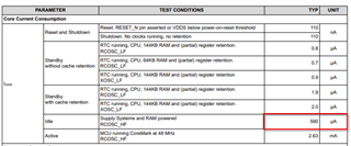
moreover the current either remains the same or even increases from 0.48mA to 0.7mA.

As for DIOs configuration, other than DIO3 which is used for TX and is defined as output, all other DIOs are defined as inputs with pullup, as follows: 

/*DIO1*/     /* CC_GP1_TP              */     GPIO_CFG_INPUT     | GPIO_CFG_IN_PU          |  GPIO_CFG_INT_DISABLE,

/*DIO2*/     /* Board_UART_RX       */     GPIO_CFG_INPUT     | GPIO_CFG_IN_PU          |  GPIO_CFG_INT_DISABLE,

*/DIO3*/     /* Board_UART_TX        */     GPIO_CFG_OUTPUT    | GPIO_CFG_OUT_HIGH,

*/*DIO4*/     /* I2C_WP                     */     GPIO_CFG_INPUT     | GPIO_CFG_IN_PU          |  GPIO_CFG_INT_DISABLE,

*/*DIO5*/ .....

To activate sleep mode, we invoke the below command via DockLight and get an ack in response: 

20/03/2023 17:16:24.779 [TX] - 06 A2 00 01 01 AA 0A
20/03/2023 17:16:55.137 [RX] - 05 01 00 00 06 0A [ATE] ACK

The command invokes the below function for entering stand by mode, cancel constraints, close uart interface and enter sleep mode.

void ATE_Io_Enter_Standby_Mode( void )
{
// PowerCC26X2_module.constraintCounts
static Semaphore_Params semParams;
static Semaphore_Struct semStruct;
static Semaphore_Handle semHandle;

//create mutex
Semaphore_Params_init(&semParams);
semParams.mode = Semaphore_Mode_BINARY;
Semaphore_construct(&semStruct, 0, &semParams);
semHandle = Semaphore_handle(&semStruct);
// generate ACK
uint8_t hpr_ack[sizeof(hpr_msg_header_t) + sizeof(hpr_payload_type_e) + sizeof(hpr_msg_payload_ack_t) + sizeof(hpr_msg_footer_t)];
hpr_ack_e response_description = HPR_ACK_MESSAGE_LEGAL;

HPR_PrepareAck((hpr_msg_t_new*)hpr_ack,response_description);
HPR_PrepareMessage((hpr_msg_t_new*)hpr_ack);
// print ACK to UART before close
UART_write(uart.driver_handle, hpr_ack, sizeof(hpr_ack));

  // wait a bit...
  for( int index = 0; index < 0xFFFF; ++index )
  {
     asm("nop");
  }
  // close UART
  UART_close(uart.driver_handle);


uint_fast32_t mask = Power_getConstraintMask();
// do the constrains clean more robust
if( mask )
{
   for (int index = 0; index < PowerCC26X2_NUMCONSTRAINTS; ++index)
  {                // do it for all constrains one after another with checking mask status
      do
      {          // PowerCC26X2_module.constraintCounts
          if( mask & (1 << index) )
         {                       // when the correcponded bit in the mask is enabled, release
                                 // the constrain, then read and check the mask once more
                 Power_releaseConstraint( index );
         }
        mask = Power_getConstraintMask();
      }
      while( mask & (1 << index) );
   }

}


if( !board_isClosedPin( Board_UART_TX ) )
{
  board_closePin( Board_UART_TX );
}
if( !board_isClosedPin( Board_UART_RX ) )
{
  board_closePin( Board_UART_RX );
}

board_openPin(Board_UART_TX, PIN_INPUT_EN | PIN_PULLUP | PIN_IRQ_DIS );
board_openPin(Board_UART_RX, PIN_INPUT_EN | PIN_PULLUP | PIN_IRQ_DIS );

sleep(0xFFFFFFFF);

//enter mutex
Semaphore_pend(semHandle, BIOS_WAIT_FOREVER);

return;
}

Assuming all power constraints are removed, what may be the reason for the current consumption not dropping and sleep mode not entering? 

The cc1312R7 was flashed with release version and the current consumption remained unchanged even after disconnecting all cables (like uart and J-Link) ,leaving only the power supply.

Note that as far as i know, the function was invoked in the past on CC1312R1 and seemed to have worked.

Thank you.

- Eran

  • Looking at the power consumption table in the datasheet:

    The closest to what you measure is marked. If you sniff (not measure directly) are the HF clock on? 

    What HW you you measuring on? The other option is an input or similar that draw current. Try to set all DIOs in high-z instead to avoid the pull-up. 

  • Hi,

    Thank you for the response.

    I have tried several methods including changing DIOs configurations to avoid pullup but the current consumption remained unchanged when trying to enter standby mode.

    However, when i added to the function above, after the call to sleep(0xFFFFFFFF),  a call to: SysCtrlStandby(false, VIMS_ON_CPU_ON_MODE, 0), things started to change and there was an impact on the current consumption, dropping it to around 150nA.


    However, as the table TheGhostOf has attached, this measurement indicates more a state of "Reset and Shutdown" than a "Standby" state, which should be around 1μA.

    When comparing this behavior, running on CC1312R7, with the behavior of CC1312R1, the CC1312R1 behaves as expected and drops to around 1μA.

    a. is it ok to use SysCtrlStandby() ?

    This API includes within a call to PRCMDeepSleep(), so the expectation is to only let the cpu sleep. 

    Any suggestions why it seems device goes into shutdown and not into sleep mode?

    b. tried comparing ti_devices_config.c used with our CC1312R1 project with the ti_devices_config.c generated by the sysconfig utility(activated from IAR) in the CC1312R7 project.

    All definitions between them seem alike other than one that exists in the CC1312R1 driver but does not exist in the CC1312R7 driver:

    #define CC1312R7:SET_CCFG_SIZE_AND_DIS_FLAGS_DIS_ALT_DCDC_SETTING  0x0

    Can this definition make the difference between the 2 CPUs? 

    (please note that "Enable DCDC" is unchecked thus SET_CCFG_MODE_CONF_DCDC_RECHARGE and SET_CCFG_MODE_CONF_DCDC_ACtive are 0x1)

    I would like to add CC1312R7:SET_CCFG_SIZE_AND_DIS_FLAGS_DIS_ALT_DCDC_SETTING to the CC1312R7 driver. Where can i find it in the sysconfig utility? 

    Thank you very much

    Best regards,

    Eran

  • Hi Eran, 

    The SET_CCFG_SIZE_AND_DIS_FLAGS_DIS_ALT_DCDC_SETTING that you refer to, doesn't seem to be a user configurable setting with sysconfig, It is not adviced to be changed. By default, this setting is set to 0.

    #define SET_CCFG_SIZE_AND_DIS_FLAGS_DIS_ALT_DCDC_SETTING    0x0    // Alternative DC/DC setting enabled
    This is found in source/ti/devicec/cc13x2x7_cc26x2x7/startup_files/ccfg.c in the SDK. This has the same default setting in both CC1312R and CC1312R7. 
    It is interesting that your previous code had to forcefully define this again in the ti_devices.config.c
    Just to debug the situation, please can you build the project once.
    Then in your sysconfig. Exclude from build the ti_devices_config.c
    Then, you can edit the previously generated ti_devices_config.c file. This is located in your CCS_project_folder/Debug/syscfg folder.
    You can add your line here and then build the project again. This file is not overwritten because you have excluded the file from build.
     The SysCtrlStandby() API from driverlib is not recommended to be used directly by the application. Please try the above change in ti_devices_config.c. I will see if there is other relevant test that can be done to check what causes the device to not enter standby but idle.  Also, jsut making sure, your debugger is not connected right?
    Regards,
    Sid
  • Hi Sid,


    Thank you very much for the response and suggestions.


     1st, let me describe our HW setup.  

    To reduce any apparent impact on the CC1312R7 measurements, it is simply mounted on a cardboard, connected to a 3V power supplier and has one JTAG interface for flashing and a UART Rx/Tx interface for communication with Docklight.

    (please refer to attachment in the e-mail thread)

     Also, for your question, we only flash the cpu with release versions so the IAR debugger is not connected for any of the tests done by ATE team.

    I have followed your instructions disabling the generation of the driver in sysconfig and adding SET_CCFG_SIZE_AND_DIS_FLAGS_DIS_ALT_DCDC_SETTING to the driver file.

    I will update when i recieve the results.  

    I would also want to talk about SysCtrlStandby(), if you may. 

    (the standby function described in the head of this post, does enter the cpu to standby for cc1313R1 but does not for cc1312R7)

    (We have the same simplified HW setup for cc1312R1)


    Since Power_releaseConstraint did not impact the standby mode, I have started experimenting with directly calling power related APIs just to see what works and what does not.

    It would seem only the call to SysCtrlStandby() did have any impact on the current consumption.

    Shouldn’t SysCtrlStandby have been called indirectly?


    Best Regards,

    Eran

  • Hi Eran,

    I want to clarify a couple of things here.

    1. Is this the only function that executes when you run this test? If you are using the drivers for peripherals like you have used for UART, you should not need to even release the constraints yourself like you have done in the application. The drivers should release the power constraints and dependencies themselves. 
    2. This leads to another question, have you set the power constraints somewhere else in the code? Is this code executing and thus disallowing standby. We should figure out what causes the chip to not allow standby rather than forcing it to standby. Using SysCtrlStandby does not seem like a good idea here.
    3. When you generated the firmware for cc1312R1 and CC1312R7, did you use the same SDK or are you using different SDK versions to generate the firmware for these two devices?
    4. Is there a way for you to retrieve the power constraint mask after UART_close()? 

    Regards,

    Sid

  • Hi Sid,

    In our current project, we use the CC1312R7 CPU within a PGH device which is connected to a panel and powered by it constantly.

    In this project, the CPU is not intended to ever go into standby mode in normal operation and will never do so in production releases.

    (However, in the future we would  likely need to use CC1312R7 with powerG detectors, which are battery powered, and then standby would be essential.)


    We currently need standby mode only for ATE multi RF test releases, for measurements of frequencies, RTCs, current consumption, etc.

    That being said, it means that for ATE purposes, the cpu will not go automatically into standby mode unless we specifically tell it to.

    That was why the constraints were released in the standby function.


    Regarding your questions,

    1. Yes. After the function exits without going to standby, the app goes into idle mode.
    2. Yes. The radio task and UART task are setting constraints prior to getting into their main loop.  

    The below functions is called to set the constraints:

    void power_setPowerConstrain( void )
    {
        //enter critical section
    #ifdef SUPPORT_TIRTOS7
            intptr_t key = GateHwi_enter(power_GateHwi_Handle);
    #else      
           UInt gateKey = GateAll_enter( gate );
    #endif  //SUPPORT_TIRTOS7
     

     //set the power constrain

     Power_setConstraint( PowerCC26XX_SB_VIMS_CACHE_RETAIN );

     Power_setConstraint( PowerCC26XX_SD_DISALLOW );

     Power_setConstraint( PowerCC26XX_SB_DISALLOW );

     Power_setConstraint( PowerCC26XX_IDLE_PD_DISALLOW );

    #if (defined(IMPROVE_POWER_CONSTRAIN) && (IMPROVE_POWER_CONSTRAIN == 1))    
            Power_setConstraint( PowerCC26XX_IDLE_PD_DISALLOW );
    #else
            Power_setConstraint( PowerCC26XX_NEED_FLASH_IN_IDLE );
    #endif 

    //exit critical section
    #ifdef SUPPORT_TIRTOS7   
            GateHwi_leave(power_GateHwi_Handle,key);   
    #else         
            GateAll_leave( gate, gateKey );
    #endif    //SUPPORT_TIRTOS7
    }        

    The radio task is also setting:
    PowerCtrlSourceSet(PWRCTRL_PWRSRC_GLDO);               // 0x00000000


     3. When we moved into CC1312R7, we have switched to SDK: simplelink_cc13xx_cc26xx_sdk_6_20_00_29.

     4. Yes, running debug captured the following mask values prior to calling UART_close():

          Mask starting with value = 31 and showed the following values, cycling in the loop:  30, 28, 24, 16, 0

    Best regards,
    Eran

  • Hi Eran, what was the SDK used to develop the application for the CC1312R? If the application level code is identical on both, we would expect the same behavior on these devices.

  • Hello Sid,

    with CC1312R1 we were using simplelink_cc13x2_26x2_sdk_4_40_04_04 as SDK.

    Best regards,

    Eran

  • I do not see the power driver source change between these two SDKs. I will check with RnD to see if there is anything else that prevents it from going to standby. But is it possible for you to test GPIO standby example from the SDK on both devices and measure current in your setup?

  • I Sid,

    I have looked at the examaples you have suggested  at: simplelink_cc13xx_cc26xx_sdk_6_20_00_29\examples\rtos\LP_CC1312R7\drivers\gpiostandby\tirtos7\iar

    They do is a simple sleep(). is this enough for simulating going into standby? 
    Also, syscfg is different from what the ATE team is using for their measurements, for example the DCDC configuration. Should i leave the syscfg unchanged for this test or adjust it for ATE purposes?

    Anyway, I can add a section to the ewp file for creating a release version and i will also need to set back an env for R1. I will respond again after ATE test these.

  • Could you outline why the DCDC settings are changed? A previous post indicate that you have altered SET_CCFG_SIZE_AND_DIS_FLAGS_DIS_ALT_DCDC_SETTING  which basically is a don't touch setting. 

    sleep() will in the example take the chip to standby (if you haven't done so, measure the current profile). RTOS will always try to take the chip down to the lowest current consumption possible and when calling sleep() here it's nothing preventing the chip to go to sleep (no drivers needing resources etc)

  • Hi,

    Sorry, I was not referring to SET_CCFG_SIZE_AND_DIS_FLAGS_DIS_ALT_DCDC_SETTING which as you said is not relevant.

    I was referring to these which do impact their various measurements:
    ATE requirements:
    #define CCFG_FORCE_VDDR_HH 0x1
    #define SET_CCFG_MODE_CONF_DCDC_RECHARGE 0x1
    #define SET_CCFG_MODE_CONF_DCDC_ACTIVE 0x1
    #define SET_CCFG_MODE_CONF_XOSC_CAP_MOD 0x0
    #define SET_CCFG_MODE_CONF_XOSC_CAPARRAY_DELTA 0x3


    TI RTOS7 gpio_standby example:
    #define CCFG_FORCE_VDDR_HH 0x0
    #define SET_CCFG_MODE_CONF_DCDC_RECHARGE 0x0
    #define SET_CCFG_MODE_CONF_DCDC_ACTIVE 0x0
    #define SET_CCFG_MODE_CONF_XOSC_CAP_MOD 0x1

  • The 4 settings you list here are user defined and dependent on your board design. You should change syscfg to reflect this 

  • thanks. i will update when ATE have results on these builds.

  • Hello Sid, 

    ATE responded that the builds, according to the examples were simulating standby mode ok, and current measurements were fine as well. 

    Summing up the tested releases:

    For CC1312R1:
    Project:  C:\ti\simplelink_cc13x2_26x2_sdk_4_40_04_04\examples\rtos\CC1312R1_LAUNCHXL\drivers\pinStandby\tirtos\iar\pinStandby_CC1312R1_LAUNCHXL_tirtos_iar.template.eww
    SDK: simplelink_cc13x2_26x2_sdk_4_40_04_04
    IAR: 8.50.1

    For CC1312R7:
    Project: 
    C:\ti\simplelink_cc13xx_cc26xx_sdk_6_20_00_29\examples\rtos\LP_CC1312R7\drivers\gpiostandby\tirtos7\iar\gpiostandby_LP_CC1312R7_tirtos7_iar.template.eww
    SDK: simplelink_cc13xx_cc26xx_sdk_6_20_00_29
    IAR: 8.50.9

  • Hi Eran, 

    To sum this up, 

    Both the boards in the out of the box SDK examples are reaching standby as expected and also the current consumption numbers are at the expected numbers?

    Now the question is, does the Sysconfig for these examples when you did the measurement differ from the Sysconfig you are using for the testing where you are not reaching standby. 

    Regards,
    Sid 

  • Hi,

    yes, according to ATE both the boards with the SDK examples reached standby. R7 dropped immediately to around 1.0 uA and R1 took a bit longer to drop  current consumption but reached 1.9uA. 

    The same SysConfig was used for R7 flashed with the sdk example and the version which is not getting into standby.

    We also tried integrating the code from the task in the example into our standby function (within attached rar file), but current showed5mA so there was again no impact.TI_SDK_drivers.rar 

  • and R1 took a bit longer to drop  current consumption but reached 1.9uA.

    How does the current draw vs time curve look like? It should be a instant drop when the chip goes to standby. If you have a slow decrease in current it could sound like some pins are not correctly defined (floating or slow discharge) 

  • Hi,
    I'm attaching the measurements captured by ATE team comparing R1 and R7 behavior. After another analysis it seems both went to sleep immediately however, there is a difference in the average current measurements and when zooming into each event pulse, the behavior seems different for some reason. 


    standby_current_R1_Vs_R7.rar

  • Hi Eran,

    In both the cases, it does seem to have reached standby. If this is the case, in your board, the cc1312r7 is capable of going into standby. 

    Please can you check what components of the two projects are re-used and what is the exact software diff between the two. When using the out of the box example, they seem to have no problem entering standby. 

    Regards,

    Sid