This thread has been locked.

If you have a related question, please click the "Ask a related question" button in the top right corner. The newly created question will be automatically linked to this question.

CC1120: It looks like there is no byte in RXFIFO.

Part Number: CC1120

Hello expertes.

I am a  person who is experimenting with the CC1120 in the environment shown in the picture below.

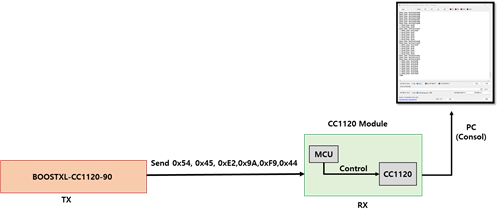
The CC1120 module acts as a RX and is composed of an mcu and a CC1120 chip, the CC1120 chip is controlled by the MCU.

The CC1120 module is manufactured, not a commercial product.

BOOSTXL-CC1120-90 is used as TX and is a commercial product of TI.

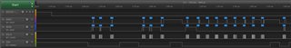
BOOSTXL-CC1120-90 interlocks with SMART RF and can transmit packets with the set Carrier Frequency through Packet TX of SMART RF in PC.

I've asked a similar question before (link below)

link : https://e2e.ti.com/support/wireless-connectivity/sub-1-ghz-group/sub-1-ghz/f/sub-1-ghz-forum/1206681/cc1120-i-have-a-problem-with-nothing-being-stored-in-the-rx-fifo/4555118#4555118

I understand that the following steps are required to rx the TX packets on the CC1120 module

1. Reset CC1120

2. Write configuration registers

3. Calibrate the synth (if autocal is not enabled)

4. Strobe SRX

5. Wait for the packet to be received (Packet received signal asserted)

6. Check if there are byte in the FIFO (the packet received signal will also be asserted if filtering took place).

7. Read as many bytes as indicated by the NUM_RXBYTES register.

Based on that content, I wrote a code.

The code operated in the main statement is as shown in the figure below.

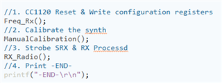
The main statement consists of the following 4 functions.

Contents of each function are as follws.

1. Freq_RX() : Function that sets the CC1120 register value in the CC1120 module. Using register values extracted from SMARTRF

2. ManualCalibration() : Calibrate the synth function. Produced by reffering to cc112x_easy_link_rx.c

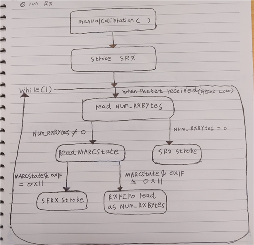
3. RX_Radio() : RX FIFO, etc. This function handles the overall contents related to RX. Produced by referring to runRX() function in cc112x_easy_link_rx.c

I think there is something wrong with the RX_Radio() function.

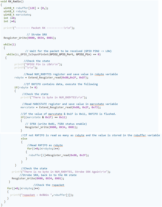
The RX_Radio() function is as follows.

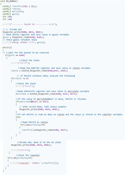
First, I strobe the SRX.

Then I checked if there are byte in the RXFIFO. (If the IOCFG2 register value in 0x06, I know that the bye is checked in RXFIFO)

Afterr that, the NUM_RXBYTES register was read, and if the value was not 0, the RXFIFO error was checked.(by check the marcstate register value & 0x1F = 0x11 )

If there was no error, the RXFIFO value was stored in the rxbuffer variable and the value was checked.

However, when reading the current NUM_RXBYTES register, even though BOOSTXL-CC1120-90 is sending packets, it continues to repeat and the value is confirmed as 0.

I'm worried that I executed the code when there is no byte in RXFIFO.

I would really appreciate it if you could let me know what went wrong in the process I was going through.

Thank you for reading this long post and any advice will be of great help to me.

                                                                                                                               - by Kim -

However, when
  • I think you have misunderstood the code.

    You should not read back register IOCFG2

    If you have programmed register IOCFG2 to be 0x06 it will always be 0x06.

    Programming the register to this value, means that the GPIO2 signal (out on a pin) will be the packet received signal. This is the signal you need to check (you need to look for a falling edge interrupt on this pin (must be connected to an input on your MCU)

    I have simplified the code I have linked to earlier:

    // Initialize MCU and peripherals
    initMCU();
    
    // Write radio registers
    registerConfig();
    
    uint8 rxBuffer[128] = {0};
    uint8 rxBytes;
    uint8 marcState;
    
    // Connect ISR function to GPIO2
    ioPinIntRegister(IO_PIN_PORT_1, GPIO2, &radioRxISR);
    
    // Interrupt on falling edge
    ioPinIntTypeSet(IO_PIN_PORT_1, GPIO2, IO_PIN_FALLING_EDGE);
    
    // Clear ISR flag
    ioPinIntClear(IO_PIN_PORT_1, GPIO2);
    
    // Enable interrupt
    ioPinIntEnable(IO_PIN_PORT_1, GPIO2);
    
    // Calibrate radio according to errata
    manualCalibration();
    
    // Set radio in RX
    trxSpiCmdStrobe(CC112X_SRX);
        
    while(1)
    {
        // Wait for falling edge interrupt on GPIO2 (IOCFG2 = 0x06)
        while(packetSemaphore != ISR_ACTION_REQUIRED);
    
        // Read number of bytes in RX FIFO
        cc112xSpiReadReg(CC112X_NUM_RXBYTES, &rxBytes, 1);
    
        // Check that we have bytes in FIFO
        if(rxBytes != 0)
        {
            // Read MARCSTATE to check for RX FIFO error
            cc112xSpiReadReg(CC112X_MARCSTATE, &marcState, 1);
    
            // Mask out MARCSTATE bits and check if we have a RX FIFO error
            if((marcState & 0x1F) == RX_FIFO_ERROR)
            {
                // Flush RX FIFO
                trxSpiCmdStrobe(CC112X_SFRX);
            }
            else
            {
                // Read n bytes from RX FIFO
                cc112xSpiReadRxFifo(rxBuffer, rxBytes);
    
                // Check CRC
                if(rxBuffer[rxBytes - 1] & 0x80)
                {
                    // Update packet counter
                    packetCounter++;
                }
            }
        }
    
        // Reset packet semaphore
        packetSemaphore = ISR_IDLE;
    
        // Set radio back in RX
        trxSpiCmdStrobe(CC112X_SRX);
    }


    When there is a falling edge interrupt on GPIO2, a packet has been received, and you can read NUM_RXBYTES, MARCSTATE and then the FIFO.

    On the SPI it looks like this when I send 0x05, 0x01, 0x02, 0x03, 0x04, x05 from SmartRF Studio

    NUM_RXBYTES is 8, meaning that there are 8 bytes in the FIFO (length byte, 5 payload bytes , 2 status bytes)

    MARCSTATES indicates that the radio is in IDLE (0x41)

    The 8 bytes in the FIFO are 

    Length: 0x05

    Payload: 0x01, 0x02, 0x03, 0x04, 0x05

    Status:0x27, 0x82

    Siri

  • Sorry for the very late reply.

    I think you gave the best answer and gave it for me to understand.

    It took me a while to build code based on your answers.

    The code I created is below.


    AS a result of executing code, it was recognized that GPIO2 became low.

    However, even though BOOSTXL-CC1120-90 is sending packets, the value of NUM_RXBYTES does not change from 0, only SRX continues to strobe.

    I tried to solve it myself based on what you told me, but I can't quite figure out what the problem is.

    I really appreciate your help.

  • I don't know if it will help, but I coded it according to the picture structure below.

  • I am still not sure your code is correct.

    In your code you will read NUM_RXBYTES every time the GPIO pin is low.

    This pin will be low most of the time (unless you are currently receiving a packet).

    What you should do is to connect this pin to a falling edge interrupt, and when this interrupt occurs, you should proceed with your code reading NUM_RXBYTES.

    If you are just checking that GPIO is 0, it will be this all the time between strobing RX and actually receiving something, so you will read NUM_RXBYTES = 0 MANY times.

    The first thing you should check (using a logic analyzer or scope) is that your GPIO pin actually goes high and then low when you are sending a packet. If it does not, it means that your radio is not able to receive any data.

    This might be HW related, or wrong settings compared to your transmitter.

    If you can see that the GPIO pin goes high and then low again, but there are still no data in the RX FIFO, it means that the packet has been discarded.

    This might be due to address filtering, packet length filtering or CRC filtering.

    Please start by monitoring the GPIOx line (IOCFGx =0x06) when your radio is in RX and you are transmitting, and confirm that this signal is getting high and low when you transmit.

    Siri

  • Thank you, now I can see what's wrong in my code .

    I think you've already told me enough how to do it, so I haven't implemented rx yet, but I'll keep trying. thank you really.

  • I will close this thread then, and you can re-open it again if you have more questions.

    Siri

  • OK Thank you very much. I will let you know when I get a results