CC1310: CC1310 - Sensor Controller Studio Pulse counter

Part Number: CC1310

Tool/software:

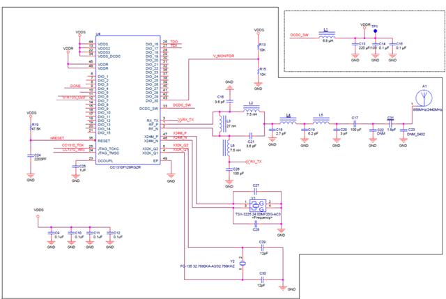
We wrote the code in Sensor Controller Studio to count pulses using the LAUNCHXL-CC1310 on the Sensor Controller pins. The code works correctly and accurately counts pulses on the launchpad. However, when we implemented the same setup on our custom-designed PCB using the same controller and applied the same pulse signal to the same pin, we encountered an issue: the pulse count is inaccurate, showing approximately 100 extra counts.We tested this on two different PCBs and observed the same issue. We also compared our PCB design with the launchpad and confirmed that the configurations are identical.Please guide me.

  • Hi Nirav,

    Have you checked the pulse signal using an oscilloscope? Do you see any difference between the Launchpad signal and the one on your PCB?

    Also, do you use the same crystals on your PCB, as the ones on the Launchpad?

    Regards,

    Arthur

  • We the crystal are the same and we interchanged the Crystal we faced the error

  • Hi Nirav,

    Can you share a schematic, or a section of the schematic with the pulse counting front-end + crystal? A pcb layout section would be interesting as well.

    Regards,

    Arthur

  • See the attched image where "Done" pin used for the powered the pulse ICs and the "STATUS LED" Will be used for the countining the pulse.

    We write code using Sensor Controller Studio. When testing with the LaunchPad, the counter value updates at one-second intervals, which is as expected. However, on our custom PCB design, we observe a higher counter value than expected.

    Interestingly, when we run the code in debug mode, the counter value is correct. But when we run the code in continuous mode (without debugging), we encounter the higher counter issue.

    Input PIN : STATUS_LED  

    Out PIN for Powered the Pulse ICs : DONE

    /***  Code for refrences  ****/

    gpioCfgMode(AUXIO_I_COUNTER_CTRL, GPIO_MODE_INPUT);   

    gpioDisableInputBuf(AUXIO_I_COUNTER_CTRL);

    gpioEnableInputBuf(AUXIO_I_COUNTER_CTRL); 

    pcntEnable(PCNT_INPUT_AUXIO_BASE + AUXIO_I_COUNTER_CTRL);// Enable PCNT (pulse counter) on the configured AUXIO pin

    gpioSetOutput(AUXIO_O_LED_CTRL); 

    fwDelayUs(100000, FW_DELAY_RANGE_100_MS); // Wait for pulses (here: 100 ms)

    pcntGetValue(state.Counter); // Read counter value

    gpioClearOutput(AUXIO_O_LED_CTRL);// Turn off an Pulse IC

    fwDelayUs(100000, FW_DELAY_RANGE_100_MS);

  • Hi,

    The RC network component values (R19 and C24 in your shared schematic) for the RESET_N pin differs from the recommended values in the LAUNCHXL-CC1310 reference design. The importance of this is discussed in the following thread:  CC1310: Rower On Reset purpose?  

    Please change them to the following:

    • R19 = 100 kOhm
    • C24 = 0.1 uF

    Regards,
    Zack