This thread has been locked.

If you have a related question, please click the "Ask a related question" button in the top right corner. The newly created question will be automatically linked to this question.

CC1101 and MSP430f6659 SPI read/write problem

Other Parts Discussed in Thread: CC1101, MSP430F6659

Hello!


I got a problem trying to configure the CC1101 module using the MSP430f6659. After initializing the microcontroller I run the function which writes not-default values to the configuration registers in CC1101 an checking whether the default values are correct something like below:

	CC1101_WriteReg(CC1101_IOCFG0, rfConfig->iocfg0);
	__delay_cycles(240);
	check = CC1101_ReadReg(CC1101_IOCFG0);
	if (check != rfConfig->iocfg0)
		DEBUG("\r\nCONFIG_ERROR iocfg0\r\n");

The problem is that when I debug the code I get weird values from the default/not changed registers like for example rcctrl1 (should be 0x41, but is 0x51). Every debug session different set of registers got wrong values.

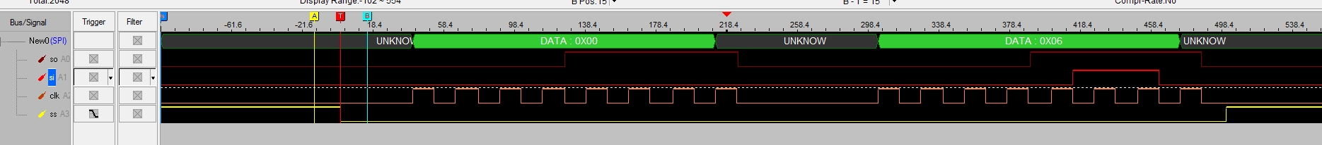
On the other hand when I simply run the code and printing the values, the IOCFG2 register is never set as I want (0x06), but got the default value and the default value of RCCTRL1 is wrong (comparing to datasheet).

I thought that it is a SPI problem, but the other registers are written/read properly. I've tried to put a delay between writing and reading the registers' values, but nothing really helped.

Any help would be very appreciated.

  • Hi

    I recommend you to use a scope to monitor your SPI lines to confirm that your SPI is implemented according to the spec. in the data sheet.

    You can also post your plots here for someone to take look at. The plot should show all 4 lines and show both write/read register.

    BR

    Siri

  • Screens from the debug (in the run time the values are like described previously - wrong):

    Write to IOCFG2 value = 0x06:

    Read of IOCFG2 seems to be OK:

    Read form RCCTRL1 (it differs from the value from data sheet):

  • Your SPI looks OK when it comes to phase and polarity. I did a test where I read the RCCTRL1 register just after a reset and I read the correct value. The plot is shown below.

    Since you are seeing different results when running from the debugger compared to free-running, I would suggest that you use a scope instead of a logic analyzer to verify that all your SPI timing is within spec.


    Also note that some registers has R0 bit fields, so if you try to write these fields to 1 you still reads back 0.

    BR

    Siri

  • I have solved the problem with wrong IOCFG2 register by extending the time between the reset and first write. But the issue with worng default values of RCCTRL1 and 0 still stands on 6 of chips I got. Do you have any ideas how to fix it?

  • Hi

    I do not understand why a delay between reset and writing to the chip. You should always poll the MISO pin to check CHIP_RDYn before starting the SCLK.

    Do you not do that in your code?

    Siri

  • Yes, but I poll the GDO2 pin. And I added a delay between the reset function (with polling for chip_rdyn) and writing a new value for IOCFG2.