This thread has been locked.

If you have a related question, please click the "Ask a related question" button in the top right corner. The newly created question will be automatically linked to this question.

CC310 low power question

Other Parts Discussed in Thread: CC1310

hi

 I want to acheive this:button pressed,enter standby;loosen button,exit standby.

My code is below:

void buttonCallbackFxn(PIN_Handle handle, PIN_Id pinId)
{
  CPUdelay(8000*50);
  if (!PIN_getInputValue(Board_BUTTON0))
  {
    Power_sleep(PowerCC26XX_STANDBY);
  }
}

static void taskFxn(UArg a0, UArg a1)
{
  PIN_setConfig(buttonPinHandle, PIN_BM_IRQ, Board_BUTTON0 | PIN_IRQ_BOTHEDGES);
  PIN_setConfig(buttonPinHandle, PINCC26XX_BM_WAKEUP, Board_BUTTON0 | PIN_IRQ_POSEDGE);
 
  while(1);
}

first of all, enable PIN interrupt as both edge, and configure posedge as wakeup.

In fact,when button pressed the first time,the current is about X uA, then loose button, current is X mA.and then press button the second time, the current is still mA, it means cannot enter standby mode the second time.!

This is strange, does any one know what is wrong with this??

Thank you !

  • Have you based your code on the pinStandby example in TI-RTOS?
  • According to the API documentation of Power_sleep():

    [...] This function is called from the power policy when it has made a decision to put the device in a specific sleep state. This function returns to the caller (the policy function) once the device has awoken from sleep.

    This function must be called with interrupts disabled, and should not be called directly by the application, or by any drivers. [...]

    TI-RTOS always puts the controller into the deepest possible sleep state when nothing else has to be done. Please also refer to the power management documentation.

  • hi richard:

    thanks for your reply.

    I modified my code like below:

    void buttonCallbackFxn(PIN_Handle handle, PIN_Id pinId)
    {
      CPUdelay(8000*50);
      if (!PIN_getInputValue(Board_BUTTON0))
      {
        PowerCC26XX_standbyPolicy();
      }
    }

    static void taskFxn(UArg a0, UArg a1)
    {
      PIN_setConfig(buttonPinHandle, PIN_BM_IRQ, Board_BUTTON0 | PIN_IRQ_BOTHEDGES);
      PIN_setConfig(buttonPinHandle, PINCC26XX_BM_WAKEUP, Board_BUTTON0 | PIN_IRQ_POSEDGE);
     
      Power_releaseConstraint(PowerCC26XX_SB_DISALLOW);
      Power_releaseConstraint(PowerCC26XX_IDLE_PD_DISALLOW);
     
      while(1);
    }

    When button pressed, current is about 200uA, loosen button,3mA,repeat press button, also 200uA.and loosen ,3mA.

    But 200uA is too high, So I followed into the PowerCC26XX_standbyPolicy function, and I found CC1310 enter Idle mode instead of standby mode.

    so, Can you pls check if it is something wrong with my code?

    Thank you!

  • What you do, looks wrong to me. Why do you call Power_releaseConstraint()? You have never set any constraints. By calling PowerCC26XX_standbyPolicy() you will likely mess up with the TI-RTOS power management.

    Correct way of using dependencies and constraints:

    void myFunctino()
    {
        Power_setDependency(PERIPHERAL);
        // Code
        // Code
        Power_releaseDependency(PERIPHERAL);
    }


    This guarantees that PERIPHERAL is switched on while the controller executes code in the lines marked with "Code". However, TI-RTOS is allowed to go to standby and hence, to power down peripheral if something in those lines blocks the execution. setDependency()/releseDependenc() could also be in separate functions, e.g. in an interrupt handler and a task.

    If you simply want to prevent the controller from going to standby, you need constraints:

    Power_setConstraint(POWERCC26XX_SB_DISALLOW);
    // Code 
    // Code
    Power_releaseConstraint(POWERCC26XX_SB_DISALLOW);

    If you want both, a peripheral to be switched on and stay on, you have to combine dependencies and constraints.

    Regarding the power consumption: Do you have the debugger attached? Then the CC1310 does not enter standby because of JTAG.

  • hi  richard

    1.  Because I set constraints in "main" before "bios_start", so I need to  release constraints before CC1310 enters standby mode.

    2.  When I  measure curernt, I disattach The debugger and remove all jumpers in P408,and the current is 200uA in low power mode, 3mA when wakeup.

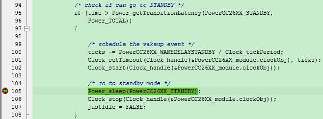
    3.  In debug mode,I followed into PowerCC26XX_standbyPolicy function, it truely enters standby,as below:

    4. My test code didn't intial any peripheral, so I think setDependency()/releseDependenc() is not needed. But , for example,if I need uart,  when uart_open, Dependency  is automatically set. So ,in your opinion, do I need to add extra setDependency before uart_open?

     Now I really have no idea about how to enter or exit standby,  what else do you suggest?

    Thank you!

  • The TI-RTOS drivers do power management automatically, so you don't need to deal with that. My comment above is valid, when you develop your own drivers or want to access hardware beyond what the existing drivers can do.

    I do still not understand, what you are going to achieve. Do you want something like that?

    .cfg file:

    // Application-specific part in the .cfg file.
    // These objects can be either created directly
    // or by the help of the (unfortunately slow) GUI.
    
    // Create a single task
    var task0Params = new Task.Params();
    task0Params.instance.name = "task0";
    task0Params.stackSize = 1024;
    Program.global.task0 = Task.create("&mainTaskFunction", task0Params);
    
    // Create a semaphore object for synchronization
    var semaphore0Params = new Semaphore.Params();
    semaphore0Params.instance.name = "semaphore0";
    semaphore0Params.mode = Semaphore.Mode_BINARY;
    Program.global.semaphore0 = Semaphore.create(null, semaphore0Params);

    main.c:

    extern Semaphore_Handle semaphore0;
    
    void buttonCallbackFxn(PIN_Handle handle, PIN_Id pinId) 
    {
      CPUdelay(8000*50);
      if (!PIN_getInputValue(Board_BUTTON0))
      {
        // Button has been pressed, notify the main task.
        Semaphore_post(semaphore0);
      }
    }
    
    void mainTaskFunction()
    {
      for (;;)
      {
        // Wait for a button press and block
        // the task.
        // Go to power-down if nothing
        // else has to be done.
        Semaphore_pend(semaphore0, BIOS_WAIT_FOREVER);
    
        // Button has been pressed, now do something.
        // ...
      }
    }

    Have you also removed all other jumpers P403-P405? Another possiblity could be floating inputs without pull-up/pull-down configuration. What does your program do? Can it really go to standby? How do you measure? Last possibility: Do you have SmartRF06 board revision 1.2.1? Then there is a linear voltage controller U504 next to the "VDD to EM" jumper which causes an additional current drop. This controller has to be removed. Revision 1.2.2 doesn't have this controller anymore.

    If you send me your binary and a description what I should do, I could also run a measurement on my desk.

  • hi richard

    thanks for your reply!

    1.I removed all other jumpers P403-P405. I series multimeter into "VDD to EM" jumper to measure current. And the voltage controller U504 on my board has been removed.

    2.My goal is to achieve this: when semaphore_pend, enters standby, when semaphore_post,exit standby. As you suggested above, I tried like this:

    (1)No peripheral initialized, code as below:

    void buttonCallbackFxn(PIN_Handle handle, PIN_Id pinId)
    {
      CPUdelay(8000*50);
      if (!PIN_getInputValue(Board_BUTTON0))
      {
        //Power_idleFunc();
        //PowerCC26XX_standbyPolicy();
        Semaphore_post(taskSem);
      }
    }

    static void taskFxn(UArg a0, UArg a1)
    {
      PIN_setConfig(buttonPinHandle, PIN_BM_IRQ, Board_BUTTON0 | PIN_IRQ_BOTHEDGES);
      PIN_setConfig(buttonPinHandle, PINCC26XX_BM_WAKEUP, Board_BUTTON0 | PIN_IRQ_POSEDGE);
     
      Power_releaseConstraint(PowerCC26XX_SB_DISALLOW);
      Power_releaseConstraint(PowerCC26XX_IDLE_PD_DISALLOW);
     
      while(1)
      {   
        Semaphore_pend(taskSem,BIOS_WAIT_FOREVER);
      }
    }

    The current is about 1uA, When wakeup, about 1mA. And CC1310 truely enters standby mode.

    (2)Initialize UART. before semaphore_pend, print information and close uart, when wakeup,open uart and print information. Code as below:

    void buttonCallbackFxn(PIN_Handle handle, PIN_Id pinId)
    {
      CPUdelay(8000*50);
      if (!PIN_getInputValue(Board_BUTTON0))
      {
        //Power_idleFunc();
        //PowerCC26XX_standbyPolicy();
        Semaphore_post(taskSem);
      }
    }

    static void taskFxn(UArg a0, UArg a1)
    {
      UartInit();
      PIN_setConfig(buttonPinHandle, PIN_BM_IRQ, Board_BUTTON0 | PIN_IRQ_BOTHEDGES);
      PIN_setConfig(buttonPinHandle, PINCC26XX_BM_WAKEUP, Board_BUTTON0 | PIN_IRQ_POSEDGE);

      while(1)
      {   
        UART_write(uart, "IN!\r\n", sizeof("IN!\r\n"));
        while(UARTBusy(UART0_BASE));
        CPUdelay(8000*200);
        UART_close(uart);  
        Power_releaseConstraint(PowerCC26XX_SB_DISALLOW);
        Power_releaseConstraint(PowerCC26XX_IDLE_PD_DISALLOW);
       
        Semaphore_pend(taskSem,BIOS_WAIT_FOREVER);
       
        UART_open(Board_UART0, &uartParams);
        UART_write(uart, "OUT!\r\n", sizeof("OUT!\r\n"));
        while(UARTBusy(UART0_BASE));
        CPUdelay(8000*200);
        Power_setConstraint(PowerCC26XX_SB_DISALLOW);
        Power_setConstraint(PowerCC26XX_IDLE_PD_DISALLOW);
      }
    }

    The current is about 700uA when semaphore_pend,and CC1310 not going to standby mode,but Idle mode instead.

    So, How should I do when some peripherals initialized? Did I miss something?


  • You are mixing the API of CC13xxWare and TI-Drivers. Here is a code snippet, how the above task should look like and how UART usage is explained in the driver documentation.

    UART_Handle uart;
    
    int main(void) {
        // Initialize the hardware
        Board_initGeneral(); // Init Power & PIN driver structures
        Board_initUART();    // Init UART driver structures
    
        // Add other initialization code here, e.g. pins
        // ...
        // Rather use a pin table instead
        // PIN_setConfig(buttonPinHandle, PIN_BM_IRQ, Board_BUTTON0 | PIN_IRQ_BOTHEDGES);
        // PIN_setConfig(buttonPinHandle, PINCC26XX_BM_WAKEUP, Board_BUTTON0 | PIN_IRQ_POSEDGE);
    
        // UART initialization
        UART_Params uartParams;
        UART_init(&uartParams);
        uartParams.baudRate = 115200;
        uartParams.writeDataMode = UART_DATA_BINARY;
        uartParams.writeMode = UART_MODE_BLOCKING;
        uart = UART_open(Board_UART0, &uartParams);
        // Assert(uart != NULL);
    
        // Start the scheduler
        BIOS_start();
    }
    
    static void taskFxn(UArg a0, UArg a1)
    {
      while(1)
      {
        // Power up the UART hardware, blocking write
        UART_write(uart, "IN!\r\n", sizeof("IN!\r\n"));
        // According to the documentation, the UART hardware is powered down at this point
    
        // The task blocks and the whole system can go to standby if nothing else runs
        Semaphore_pend(taskSem, BIOS_WAIT_FOREVER);
        // Now the system is powered up again
    
        // The UART hardware is powered up again, blocking write
        UART_write(uart, "OUT!\r\n", sizeof("OUT!\r\n"));
        // The UART hardware is powered down
      }
    }

    Does this solve your current consumption issue?

  • hi richard:

    thanks for your help.

    As you suggested, the current is also very high: 700-800uA.

    I tried at the newest TI-RTOS version V 2,20, the result is the same.

  • hi
    This issue has been solved.
    Execute Event_pend() instead of Semphore_pend() before entering standby, and when button pressed, execute event_post();
    The current is about 1-2uA.
  • Hi,
    I don't understand how your could solve the issue by simply replacing Semaphore with the Event module. Feel free to elaborate on that. Otherwise I am glad to hear that you could solve the problem.
  • hi richard

    It's true that I simply replacing Semaphore with the Event module that makes the current lower.

    Perhaps the Semaphore module is not as stable as the Event module.

    Thanks!